HP Pavilion 14-c000 HP Pavilion 14 Chromebook Maintenance and Service Guide - Page 55
Display Assembly, Description, Spare part number, Antenna Kit, Display Panel Cable Kit, Back cover
 |
View all HP Pavilion 14-c000 manuals
Add to My Manuals
Save this manual to your list of manuals |
Page 55 highlights
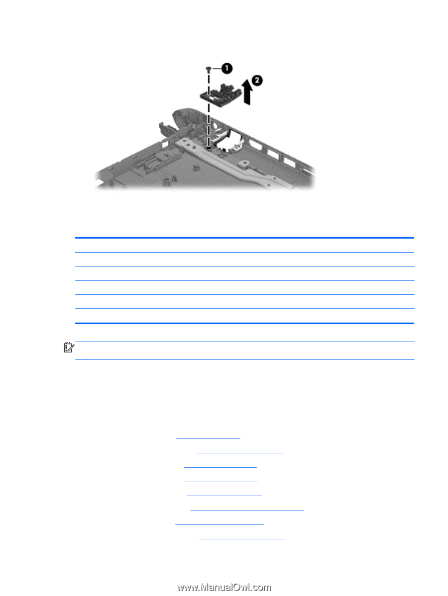
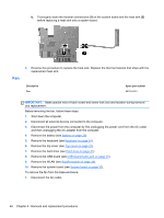
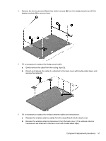
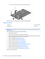
2. Lift the RJ-45 cover (2) to remove it from the base enclosure. Reverse these procedures to replace the RJ-45 cover. Display Assembly Description Antenna Kit (includes left and right wireless antenna cables and transceivers) Display Panel Cable Kit (includes display panel cable and webcam/microphone module cable) Back cover, sparkling black Display Hinge Kit (includes left and right display hinges and brackets) Webcam/microphone module Spare part number 697913-001 697911-001 708133-001 697908-001 697903-001 IMPORTANT: Make special note of each screw and screw lock size and location during removal and replacement. Before removing the display assembly, follow these steps: 1. Shut down the computer. 2. Disconnect all external devices connected to the computer. 3. Disconnect the power from the computer by first unplugging the power cord from the AC outlet and then unplugging the AC adapter from the computer. 4. Remove the battery (see Battery on page 20). 5. Remove the display panel (see Display panel on page 22). 6. Remove the keyboard (see Keyboard on page 24). 7. Remove the top cover (see Top cover on page 27). 8. Remove the hard drive (see Hard drive on page 31). 9. Remove the USB board (see USB board/Audio jack on page 33). 10. Remove the WLAN (see WLAN module on page 34). 11. Remove the system board (see System board on page 37). Component replacement procedures 49
-
 1
1 -
2
-
3
-
4
-
5
-
6
-
7
-
8
-
9
-
10
-
11
-
12
-
13
-
14
-
15
-
16
-
17
-
18
-
19
-
20
-
21
-
22
-
23
-
24
-
25
-
26
-
27
-
28
-
29
-
30
-
31
-
32
-
33
-
34
-
35
-
36
-
37
-
38
-
39
-
40
-
41
-
42
-
43
-
44
-
45
-
46
-
47
-
48
-
49
-
 50
50 -
 51
51 -
 52
52 -
 53
53 -
 54
54 -
 55
55 -
 56
56 -
 57
57 -
 58
58 -
 59
59 -
 60
60 -
61
-
62
-
63
-
64
-
65
-
66
-
67
-
68
-
69
 |
 |