HP Pavilion 14-v200 Pavilion 14 Notebook PC Maintenance and Service Guide - Page 16
Left side
 |
View all HP Pavilion 14-v200 manuals
Add to My Manuals
Save this manual to your list of manuals |
Page 16 highlights
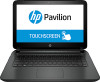
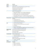
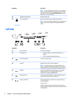
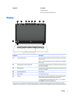
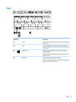
Component (6) Optical drive eject button (7) Security cable slot Left side Description NOTE: For disc compatibility information, go to the Help and Support web page. Follow the web page instructions to select your computer model. Select Drivers & Downloads, and then follow the on-screen instructions. Releases the disc tray. Attaches an optional security cable to the computer. NOTE: The security cable is designed to act as a deterrent, but it may not prevent the computer from being mishandled or stolen. Component (1) (2) Power connector AC adapter light (3) RJ-45 (network) jack (4) Vents (2) (5) HDMI port (6) USB 3.0 ports (2) (7) Memory card reader 6 Chapter 2 External component identification Description Connects an AC adapter. ● On: The AC adapter is connected and the battery is charged. ● Off: The computer is using battery power. Connects a network cable. Enable airflow to cool internal components. NOTE: The computer fan starts up automatically to cool internal components and prevent overheating. It is normal for the internal fan to cycle on and off during routine operation. Connects an optional video or audio device, such as a highdefinition television, any compatible digital or audio component, or a high-speed HDMI device. Connect an optional USB device, such as a keyboard, mouse, external drive, printer, scanner or USB hub. Reads optional memory cards that store, manage, share, or access information. To insert a card: Hold the card label-side up, with connectors facing the slot, insert the card into the slot, and then push in on the card until it is firmly seated.
-
 1
1 -
2
-
3
-
4
-
5
-
6
-
7
-
8
-
9
-
10
-
 11
11 -
 12
12 -
 13
13 -
 14
14 -
 15
15 -
 16
16 -
 17
17 -
 18
18 -
 19
19 -
 20
20 -
 21
21 -
22
-
23
-
24
-
25
-
26
-
27
-
28
-
29
-
30
-
31
-
32
-
33
-
34
-
35
-
36
-
37
-
38
-
39
-
40
-
41
-
42
-
43
-
44
-
45
-
46
-
47
-
48
-
49
-
50
-
51
-
52
-
53
-
54
-
55
-
56
-
57
-
58
-
59
-
60
-
61
-
62
-
63
-
64
-
65
-
66
-
67
-
68
-
69
-
70
-
71
-
72
-
73
-
74
-
75
-
76
-
77
-
78
-
79
-
80
-
81
-
82
-
83
-
84
-
85
-
86
-
87
-
88
-
89
-
90
-
91
-
92
-
93
-
94
-
95
-
96
-
97
-
98
-
99
-
100
-
101
-
102
-
103
-
104
-
105
-
106
 |
 |