HP Pavilion 15-ab200 Maintenance and Service Guide - Page 81
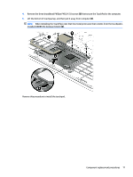
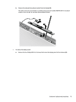
Remove the two Phillips PM2.5×5.0 screws, Position the computer on its side, partially open.
 |
View all HP Pavilion 15-ab200 manuals
Add to My Manuals
Save this manual to your list of manuals |
Page 81 highlights
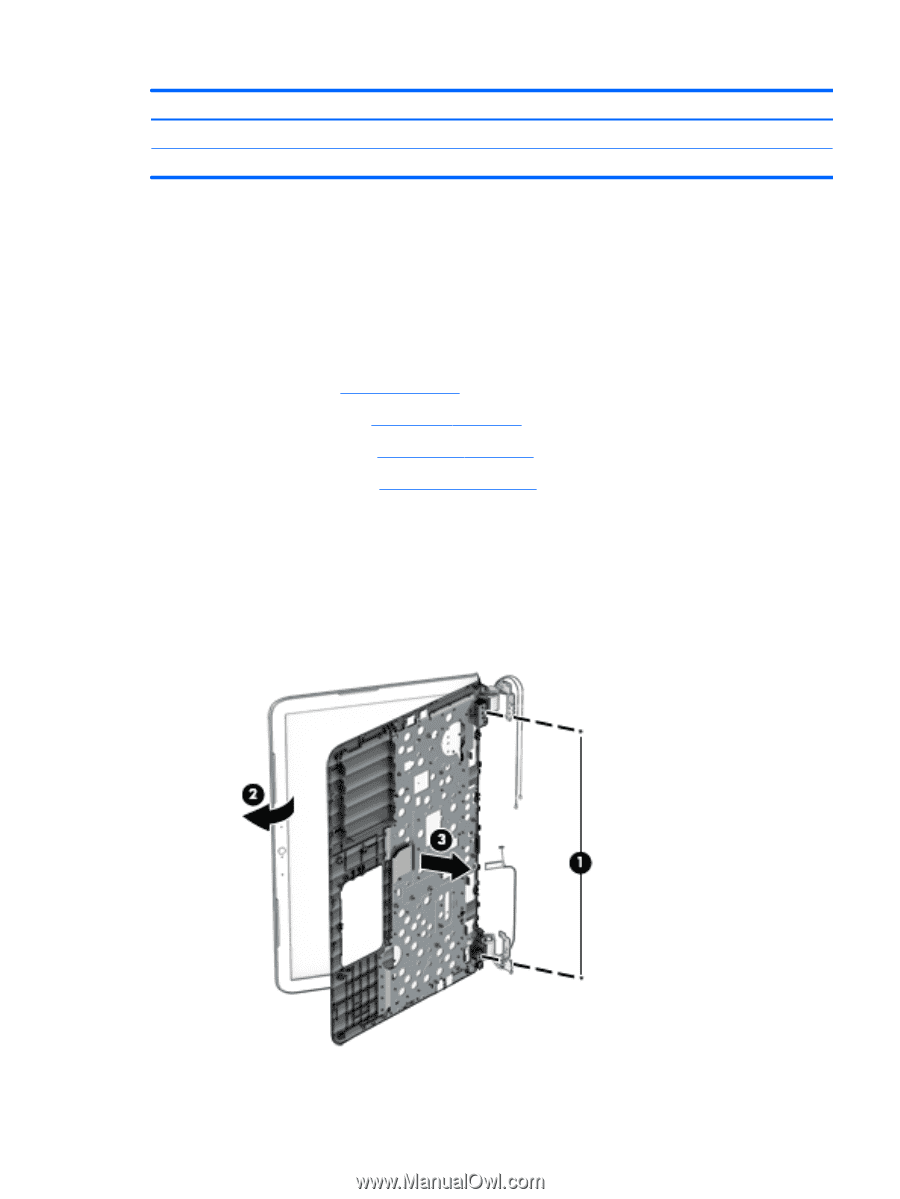
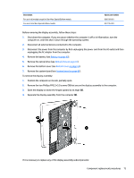
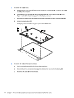
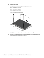
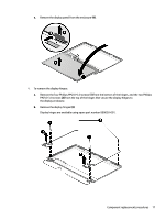
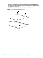
Description For use in all models except for Star Wars Special Edition models For use in Star Wars Special Edition models Spare part number 806758-001 837745-001 Before removing the display assembly, follow these steps: 1. Shut down the computer. If you are unsure whether the computer is off or in Hibernation, turn the computer on, and then shut it down through the operating system. 2. Disconnect all external devices connected to the computer. 3. Disconnect the power from the computer by first unplugging the power cord from the AC outlet and then unplugging the AC adapter from the computer. 4. Remove the battery (see Battery on page 40). 5. Remove the optical drive (see Optical drive on page 41). 6. Remove the bottom cover (see Bottom cover on page 44). 7. Remove the system board (see System board on page 62). To remove the display assembly: 1. Position the computer on its side, partially open. 2. Remove the two Phillips PM2.5×5.0 screws (1) that secure the display assembly to the computer. 3. Open the display to rotate the hinges upward to an angle (2). 4. Separate the display assembly from the computer (3). If it is necessary to replace any of the display assembly subcomponents: Component replacement procedures 73
-
 1
1 -
2
-
3
-
4
-
5
-
6
-
7
-
8
-
9
-
10
-
11
-
12
-
13
-
14
-
15
-
16
-
17
-
18
-
19
-
20
-
21
-
22
-
23
-
24
-
25
-
26
-
27
-
28
-
29
-
30
-
31
-
32
-
33
-
34
-
35
-
36
-
37
-
38
-
39
-
40
-
41
-
42
-
43
-
44
-
45
-
46
-
47
-
48
-
49
-
50
-
51
-
52
-
53
-
54
-
55
-
56
-
57
-
58
-
59
-
60
-
61
-
62
-
63
-
64
-
65
-
66
-
67
-
68
-
69
-
70
-
71
-
72
-
73
-
74
-
75
-
 76
76 -
 77
77 -
 78
78 -
 79
79 -
 80
80 -
 81
81 -
 82
82 -
 83
83 -
 84
84 -
 85
85 -
 86
86 -
87
-
88
-
89
-
90
-
91
-
92
-
93
-
94
-
95
-
96
-
97
-
98
-
99
-
100
-
101
-
102
-
103
-
104
-
105
-
106
-
107
-
108
-
109
-
110
-
111
-
112
-
113
-
114
-
115
-
116
-
117
-
118
-
119
-
120
-
121
-
122
-
123
-
124
-
125
-
126
-
127
-
128
-
129
-
130
-
131
-
132
-
133
-
134
-
135
-
136
-
137
-
138
-
139
-
140
-
141
-
142
 |
 |