HP Pavilion 15-ab200 Maintenance and Service Guide - Page 90
disconnect the display cable
 |
View all HP Pavilion 15-ab200 manuals
Add to My Manuals
Save this manual to your list of manuals |
Page 90 highlights
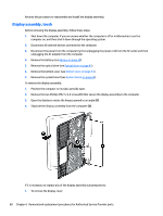
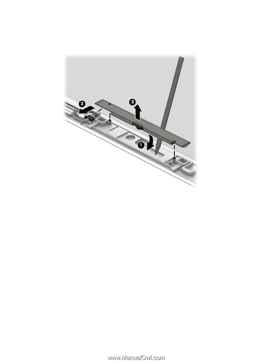
d. Remove the webcam/microphone module from the display (3). The webcam for touch displays is available using spare part number 810961-001 for standard models or 837746-001 for Star Wars Special Edition models. 3. To remove the display panel: a. Lift the tape that secures the display cable to the connector on the back of the panel (1), and then disconnect the display cable (2). b. Remove the two Phillips PM2.0×1.5 screws (3) that secure the display panel to the bottom of the enclosure. c. Remove the two Phillips PM2.0×2.0 screws (4) that secure the display panel to the top of the enclosure. 82 Chapter 6 Removal and replacement procedures for Authorized Service Provider parts
-
 1
1 -
2
-
3
-
4
-
5
-
6
-
7
-
8
-
9
-
10
-
11
-
12
-
13
-
14
-
15
-
16
-
17
-
18
-
19
-
20
-
21
-
22
-
23
-
24
-
25
-
26
-
27
-
28
-
29
-
30
-
31
-
32
-
33
-
34
-
35
-
36
-
37
-
38
-
39
-
40
-
41
-
42
-
43
-
44
-
45
-
46
-
47
-
48
-
49
-
50
-
51
-
52
-
53
-
54
-
55
-
56
-
57
-
58
-
59
-
60
-
61
-
62
-
63
-
64
-
65
-
66
-
67
-
68
-
69
-
70
-
71
-
72
-
73
-
74
-
75
-
76
-
77
-
78
-
79
-
80
-
81
-
82
-
83
-
84
-
 85
85 -
 86
86 -
 87
87 -
 88
88 -
 89
89 -
 90
90 -
 91
91 -
 92
92 -
 93
93 -
 94
94 -
 95
95 -
96
-
97
-
98
-
99
-
100
-
101
-
102
-
103
-
104
-
105
-
106
-
107
-
108
-
109
-
110
-
111
-
112
-
113
-
114
-
115
-
116
-
117
-
118
-
119
-
120
-
121
-
122
-
123
-
124
-
125
-
126
-
127
-
128
-
129
-
130
-
131
-
132
-
133
-
134
-
135
-
136
-
137
-
138
-
139
-
140
-
141
-
142
 |
 |
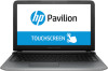
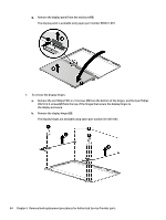
d.
Remove the webcam/microphone module from the display
(3)
.
The webcam for touch displays is available using spare part number 810961-001 for standard
models or 837746-001 for Star Wars Special Edition models.
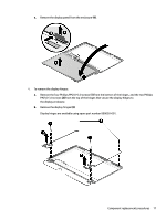
3.
To remove the display panel:
a.
Lift the tape that secures the display cable to the connector on the back of the panel
(1)
, and then
disconnect the display cable
(2)
.
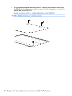
b.
Remove the two Phillips PM2.0×1.5 screws
(3)
that secure the display panel to the bottom of the
enclosure.
c.
Remove the two Phillips PM2.0×2.0 screws
(4)
that secure the display panel to the top of the
enclosure.
82
Chapter 6
Removal and replacement procedures for Authorized Service Provider parts