HP Pavilion 15-b100 HP Pavilion 15 Sleekbook Maintenance and Service Guide - Page 68
Display assembly, Remove the Phillips M screw
 |
View all HP Pavilion 15-b100 manuals
Add to My Manuals
Save this manual to your list of manuals |
Page 68 highlights
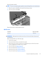
8. Remove the USB board (see USB board on page 41). 9. Remove the WLAN (see WLAN module on page 42). 10. Remove the system board (see System board on page 45). Remove the RJ-45 cover: 1. Remove the Phillips M screw (1) for the RJ-45 cover. 2. Lift the RJ-45 assembly (2) to remove it from the base enclosure. Reverse these procedures to replace the RJ-45 assembly. Display assembly NOTE: The display assembly is spared at the subcomponent level only. For more display assembly spare part information, see the individual removal subsections. IMPORTANT: Make special note of each screw and screw lock size and location during removal and replacement. Before removing the display assembly, follow these steps: 1. Shut down the computer. 2. Disconnect all external devices connected to the computer. 3. Disconnect the power from the computer by first unplugging the power cord from the AC outlet and then unplugging the AC adapter from the computer. 4. Remove the battery (see Battery on page 30). 5. Remove the keyboard (see Keyboard on page 31). 6. Remove the top cover (see Top cover on page 35). 7. Remove the hard drive (see Hard drive on page 39). 8. Remove the USB board (see USB board on page 41). 60 Chapter 4 Removal and replacement procedures
-
 1
1 -
2
-
3
-
4
-
5
-
6
-
7
-
8
-
9
-
10
-
11
-
12
-
13
-
14
-
15
-
16
-
17
-
18
-
19
-
20
-
21
-
22
-
23
-
24
-
25
-
26
-
27
-
28
-
29
-
30
-
31
-
32
-
33
-
34
-
35
-
36
-
37
-
38
-
39
-
40
-
41
-
42
-
43
-
44
-
45
-
46
-
47
-
48
-
49
-
50
-
51
-
52
-
53
-
54
-
55
-
56
-
57
-
58
-
59
-
60
-
61
-
62
-
 63
63 -
 64
64 -
 65
65 -
 66
66 -
 67
67 -
 68
68 -
 69
69 -
 70
70 -
 71
71 -
 72
72 -
 73
73 -
74
-
75
-
76
-
77
-
78
-
79
-
80
-
81
-
82
-
83
-
84
-
85
-
86
-
87
-
88
-
89
-
90
-
91
-
92
-
93
-
94
-
95
-
96
 |
 |
