HP Pavilion 15-b100 HP Pavilion 15 Sleekbook Maintenance and Service Guide - Page 69
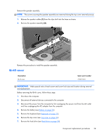
Remove the screw covers, that secure the display assembly to the base enclosure.
 |
View all HP Pavilion 15-b100 manuals
Add to My Manuals
Save this manual to your list of manuals |
Page 69 highlights
9. Remove the WLAN (see WLAN module on page 42). 10. Remove the system board (see System board on page 45). Remove the display assembly: CAUTION: Support the display assembly when removing the following screws. Failure to support the display assembly can result in damage to the display assembly and other computer components. 1. Remove the five Phillips screws (1) that secure the display assembly to the base enclosure. 2. Remove the display assembly (2). 3. If it is necessary to replace the display bezel or any of the display assembly subcomponents: a. Remove the screw covers (1). b. Remove the two Phillips screws (2) that secure the display bezel to the display assembly. Component replacement procedures 61
-
 1
1 -
2
-
3
-
4
-
5
-
6
-
7
-
8
-
9
-
10
-
11
-
12
-
13
-
14
-
15
-
16
-
17
-
18
-
19
-
20
-
21
-
22
-
23
-
24
-
25
-
26
-
27
-
28
-
29
-
30
-
31
-
32
-
33
-
34
-
35
-
36
-
37
-
38
-
39
-
40
-
41
-
42
-
43
-
44
-
45
-
46
-
47
-
48
-
49
-
50
-
51
-
52
-
53
-
54
-
55
-
56
-
57
-
58
-
59
-
60
-
61
-
62
-
63
-
 64
64 -
 65
65 -
 66
66 -
 67
67 -
 68
68 -
 69
69 -
 70
70 -
 71
71 -
 72
72 -
 73
73 -
 74
74 -
75
-
76
-
77
-
78
-
79
-
80
-
81
-
82
-
83
-
84
-
85
-
86
-
87
-
88
-
89
-
90
-
91
-
92
-
93
-
94
-
95
-
96
 |
 |

9.
Remove the WLAN (see
WLAN module
on page
42
).
10.
Remove the system board (see
System board
on page
45
).
Remove the display assembly:
CAUTION:
Support the display assembly when removing the following screws. Failure to support
the display assembly can result in damage to the display assembly and other computer components.
1.
Remove the five Phillips screws
(1)
that secure the display assembly to the base enclosure.
2.
Remove the display assembly
(2)
.
3.
If it is necessary to replace the display bezel or any of the display assembly subcomponents:
a.
Remove the screw covers
(1)
.
b.
Remove the two Phillips screws
(2)
that secure the display bezel to the display assembly.
Component replacement procedures
61