HP Pavilion dm4-2000 HP Pavilion dm4 Entertainment PC - Maintenance and Servic - Page 67
built into the base enclosure., Remove the wireless antenna cables from the hole
 |
View all HP Pavilion dm4-2000 manuals
Add to My Manuals
Save this manual to your list of manuals |
Page 67 highlights
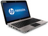
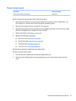
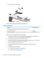
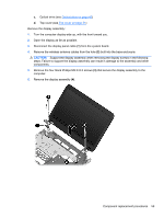
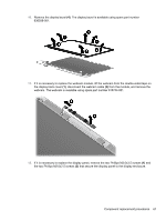
c. Optical drive (see Optical drive on page 47) d. Top cover (see Top cover on page 51) Remove the display assembly: 1. Turn the computer display-side up, with the front toward you. 2. Open the display as far as possible. 3. Disconnect the display panel cable (1) from the system board. 4. Remove the wireless antenna cables from the hole (2) built into the base enclosure. CAUTION: Support the display assembly when removing the display screws in the following steps. Failure to support the display assembly can result in damage to the assembly and other components. 5. Remove the four black Phillips M2.5×6.5 screws (3) that secure the display assembly to the computer. 6. Remove the display assembly (4). Component replacement procedures 59
-
 1
1 -
2
-
3
-
4
-
5
-
6
-
7
-
8
-
9
-
10
-
11
-
12
-
13
-
14
-
15
-
16
-
17
-
18
-
19
-
20
-
21
-
22
-
23
-
24
-
25
-
26
-
27
-
28
-
29
-
30
-
31
-
32
-
33
-
34
-
35
-
36
-
37
-
38
-
39
-
40
-
41
-
42
-
43
-
44
-
45
-
46
-
47
-
48
-
49
-
50
-
51
-
52
-
53
-
54
-
55
-
56
-
57
-
58
-
59
-
60
-
61
-
 62
62 -
 63
63 -
 64
64 -
 65
65 -
 66
66 -
 67
67 -
 68
68 -
 69
69 -
 70
70 -
 71
71 -
 72
72 -
73
-
74
-
75
-
76
-
77
-
78
-
79
-
80
-
81
-
82
-
83
-
84
-
85
-
86
-
87
-
88
-
89
-
90
-
91
-
92
-
93
-
94
-
95
-
96
-
97
-
98
-
99
-
100
-
101
-
102
-
103
-
104
-
105
-
106
-
107
-
108
-
109
-
110
-
111
-
112
-
113
-
114
-
115
-
116
 |
 |

c.
Optical drive (see
Optical drive
on page
47
)
d.
Top cover (see
Top cover
on page
51
)
Remove the display assembly:
1.
Turn the computer display-side up, with the front toward you.
2.
Open the display as far as possible.
3.
Disconnect the display panel cable
(1)
from the system board.
4.
Remove the wireless antenna cables from the hole
(2)
built into the base enclosure.
CAUTION:
Support the display assembly when removing the display screws in the following
steps. Failure to support the display assembly can result in damage to the assembly and other
components.
5.
Remove the four black Phillips M2.5×6.5 screws
(3)
that secure the display assembly to the
computer.
6.
Remove the display assembly
(4)
.
Component replacement procedures
59