HP Pavilion dm4-2000 HP Pavilion dm4 Entertainment PC - Maintenance and Servic - Page 74
Power connector cable, Turn the computer upright with the right side toward you.
 |
View all HP Pavilion dm4-2000 manuals
Add to My Manuals
Save this manual to your list of manuals |
Page 74 highlights
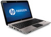
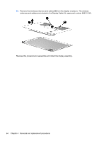
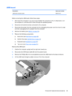
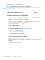
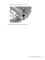
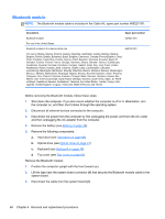
Reverse this procedure to install the USB board. NOTE: When reinstalling note that the screw goes into the upper hole. Power connector cable Description Power connector cable (includes cable and connector) Spare part number 608273-001 Before removing the power connector cable, follow these steps: 1. Shut down the computer. If you are unsure whether the computer is off or in Hibernation, turn the computer on, and then shut it down through the operating system. 2. Disconnect all external devices connected to the computer. 3. Disconnect the power from the computer by first unplugging the power cord from the AC outlet and then unplugging the AC adapter from the computer. 4. Remove the battery (see Battery on page 38). 5. Remove the following components: a. Hard drive (see Hard drive on page 45) b. Optical drive (select models only) (see Optical drive on page 47) c. Keyboard (see Keyboard on page 49) d. Top cover (see Top cover on page 51) e. USB board (see USB board on page 65) Remove the power connector cable: 1. Turn the computer upright with the right side toward you. 2. Disconnect the power connector cable (1) from the system board. 3. Remove the two Phillips M2.5×5.0 screws (2) that secure the power connector cable to the base enclosure. 4. Lift the bracket from the connector (3). 66 Chapter 4 Removal and replacement procedures
-
 1
1 -
2
-
3
-
4
-
5
-
6
-
7
-
8
-
9
-
10
-
11
-
12
-
13
-
14
-
15
-
16
-
17
-
18
-
19
-
20
-
21
-
22
-
23
-
24
-
25
-
26
-
27
-
28
-
29
-
30
-
31
-
32
-
33
-
34
-
35
-
36
-
37
-
38
-
39
-
40
-
41
-
42
-
43
-
44
-
45
-
46
-
47
-
48
-
49
-
50
-
51
-
52
-
53
-
54
-
55
-
56
-
57
-
58
-
59
-
60
-
61
-
62
-
63
-
64
-
65
-
66
-
67
-
68
-
 69
69 -
 70
70 -
 71
71 -
 72
72 -
 73
73 -
 74
74 -
 75
75 -
 76
76 -
 77
77 -
 78
78 -
 79
79 -
80
-
81
-
82
-
83
-
84
-
85
-
86
-
87
-
88
-
89
-
90
-
91
-
92
-
93
-
94
-
95
-
96
-
97
-
98
-
99
-
100
-
101
-
102
-
103
-
104
-
105
-
106
-
107
-
108
-
109
-
110
-
111
-
112
-
113
-
114
-
115
-
116
 |
 |
