HP Pavilion dm4-2000 HP Pavilion dm4 Entertainment PC - Maintenance and Servic - Page 80
System board, Remove the following components
 |
View all HP Pavilion dm4-2000 manuals
Add to My Manuals
Save this manual to your list of manuals |
Page 80 highlights
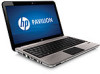
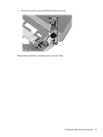
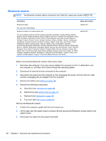
System board NOTE: All system board kits include replacement thermal material. Description Spare part number System board (includes replacement thermal material) for use in models equipped with 1 GB of HD6470 discrete graphics memory 636944-001 System board HM65 UMA 636945-001 System board HM65 UMA graphics memory for use with computer models with the Intel i3 2310M 656092-001 processor When replacing the system board, be sure that the following components are removed from the defective system board and installed on the replacement system board: ● RTC battery (see RTC battery on page 41) ● Memory modules (see Memory module on page 39) ● WLAN module (see WLAN module on page 42) ● Fan/heat sink assembly (see Fan/heat sink assembly on page 74) ● Processor (see Processor on page 79) Before removing the system board, follow these steps: 1. Shut down the computer. If you are unsure whether the computer is off or in Hibernation, turn the computer on, and then shut it down through the operating system. 2. Disconnect all external devices connected to the computer. 3. Disconnect the power from the computer by first unplugging the power cord from the AC outlet and then unplugging the AC adapter from the computer. 4. Remove the battery (see Battery on page 38). 5. Remove the following components: a. Hard drive (see Hard drive on page 45) b. WLAN module (see WLAN module on page 42) c. Optical drive (see Optical drive on page 47) d. Keyboard (see Keyboard on page 49) e. Top cover (see Top cover on page 51) f. Speaker assembly (see Speaker assembly on page 70) g. Display assembly (see Display assembly on page 58) h. USB board (see USB board on page 65) 72 Chapter 4 Removal and replacement procedures
-
 1
1 -
2
-
3
-
4
-
5
-
6
-
7
-
8
-
9
-
10
-
11
-
12
-
13
-
14
-
15
-
16
-
17
-
18
-
19
-
20
-
21
-
22
-
23
-
24
-
25
-
26
-
27
-
28
-
29
-
30
-
31
-
32
-
33
-
34
-
35
-
36
-
37
-
38
-
39
-
40
-
41
-
42
-
43
-
44
-
45
-
46
-
47
-
48
-
49
-
50
-
51
-
52
-
53
-
54
-
55
-
56
-
57
-
58
-
59
-
60
-
61
-
62
-
63
-
64
-
65
-
66
-
67
-
68
-
69
-
70
-
71
-
72
-
73
-
74
-
 75
75 -
 76
76 -
 77
77 -
 78
78 -
 79
79 -
 80
80 -
 81
81 -
 82
82 -
 83
83 -
 84
84 -
 85
85 -
86
-
87
-
88
-
89
-
90
-
91
-
92
-
93
-
94
-
95
-
96
-
97
-
98
-
99
-
100
-
101
-
102
-
103
-
104
-
105
-
106
-
107
-
108
-
109
-
110
-
111
-
112
-
113
-
114
-
115
-
116
 |
 |
