HP Pavilion dv7-4200 HP Pavilion dv7 Entertainment PC - Maintenance and Servic - Page 89
Remove the system board, Disconnect the following cables from the system board
 |
View all HP Pavilion dv7-4200 manuals
Add to My Manuals
Save this manual to your list of manuals |
Page 89 highlights
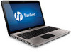
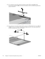
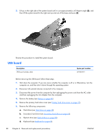
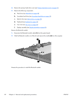
5. Remove the primary hard drive cover (see Primary hard drive cover on page 47). 6. Remove the following components: a. Hard drive (see Hard drive on page 48). b. Remove the secondary hard drive (see Secondary hard drive on page 50). c. Optical drive (see Optical drive on page 58) d. Keyboard (see Keyboard on page 60) e. Top cover (see Top cover on page 62) f. Display assembly (see Display assembly on page 68) When replacing the system board, be sure that the following components are removed from the defective system board and installed on the replacement system board: ● RTC battery (see RTC battery on page 56) ● Memory module (see Memory module on page 57) ● WLAN module (see WLAN module on page 52) ● Fan/heat sink assembly (see Fan/heat sink assembly on page 88) ● Processor (see Processor on page 93) Remove the system board: 1. Disconnect the following cables from the system board: (1) USB board cable (2) Power connector cable (3) Subwoofer cable (4) Speaker cable 2. Remove the two Phillips PM2.5×5.0 screws (1) that secure the system board to the base enclosure. ENWW Component replacement procedures 79
-
 1
1 -
2
-
3
-
4
-
5
-
6
-
7
-
8
-
9
-
10
-
11
-
12
-
13
-
14
-
15
-
16
-
17
-
18
-
19
-
20
-
21
-
22
-
23
-
24
-
25
-
26
-
27
-
28
-
29
-
30
-
31
-
32
-
33
-
34
-
35
-
36
-
37
-
38
-
39
-
40
-
41
-
42
-
43
-
44
-
45
-
46
-
47
-
48
-
49
-
50
-
51
-
52
-
53
-
54
-
55
-
56
-
57
-
58
-
59
-
60
-
61
-
62
-
63
-
64
-
65
-
66
-
67
-
68
-
69
-
70
-
71
-
72
-
73
-
74
-
75
-
76
-
77
-
78
-
79
-
80
-
81
-
82
-
83
-
 84
84 -
 85
85 -
 86
86 -
 87
87 -
 88
88 -
 89
89 -
 90
90 -
 91
91 -
 92
92 -
 93
93 -
 94
94 -
95
-
96
-
97
-
98
-
99
-
100
-
101
-
102
-
103
-
104
-
105
-
106
-
107
-
108
-
109
-
110
-
111
-
112
-
113
-
114
-
115
-
116
-
117
-
118
-
119
-
120
-
121
-
122
-
123
-
124
-
125
-
126
-
127
-
128
-
129
-
130
-
131
-
132
-
133
-
134
-
135
-
136
-
137
-
138
-
139
-
140
-
141
 |
 |
