HP Pavilion dv7-4200 HP Pavilion dv7 Entertainment PC - Maintenance and Servic - Page 99
Steps 1 through 4 apply only to models with discrete subsystem memory on the system board.
 |
View all HP Pavilion dv7-4200 manuals
Add to My Manuals
Save this manual to your list of manuals |
Page 99 highlights
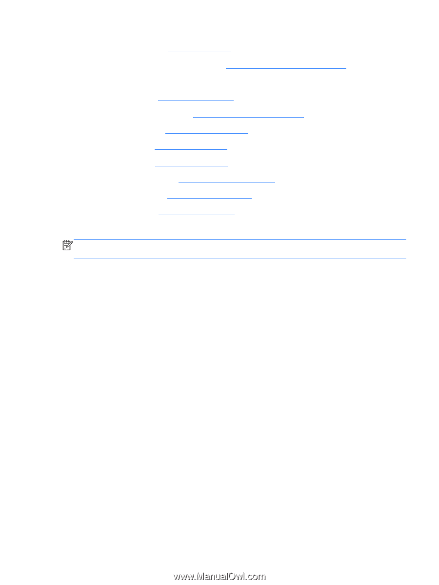
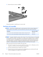
4. Remove the battery (see Battery on page 46). 5. Remove the primary hard drive cover (see Primary hard drive cover on page 47). 6. Remove the following components: a. Hard drive (see Hard drive on page 48). b. Secondary hard drive (see Secondary hard drive on page 50). c. Optical drive (see Optical drive on page 58). d. Keyboard (see Keyboard on page 60). e. Top cover (see Top cover on page 62). f. Display assembly (see Display assembly on page 68). g. System board (see System board on page 78). h. USB board (see USB board on page 80). Remove the fan/heat sink assembly: NOTE: Steps 1 through 4 apply only to models with discrete subsystem memory on the system board. See steps 5 through 8 apply only to models with UMA subsystem memory on the system board. 1. Turn the system board upside down, with the expansion port and external monitor port toward you. 2. Loosen the seven PM2.5×3.0 Phillips captive screws (1) that secure the fan/heat sink assembly to the system board. ENWW Component replacement procedures 89
-
 1
1 -
2
-
3
-
4
-
5
-
6
-
7
-
8
-
9
-
10
-
11
-
12
-
13
-
14
-
15
-
16
-
17
-
18
-
19
-
20
-
21
-
22
-
23
-
24
-
25
-
26
-
27
-
28
-
29
-
30
-
31
-
32
-
33
-
34
-
35
-
36
-
37
-
38
-
39
-
40
-
41
-
42
-
43
-
44
-
45
-
46
-
47
-
48
-
49
-
50
-
51
-
52
-
53
-
54
-
55
-
56
-
57
-
58
-
59
-
60
-
61
-
62
-
63
-
64
-
65
-
66
-
67
-
68
-
69
-
70
-
71
-
72
-
73
-
74
-
75
-
76
-
77
-
78
-
79
-
80
-
81
-
82
-
83
-
84
-
85
-
86
-
87
-
88
-
89
-
90
-
91
-
92
-
93
-
 94
94 -
 95
95 -
 96
96 -
 97
97 -
 98
98 -
 99
99 -
 100
100 -
 101
101 -
 102
102 -
 103
103 -
 104
104 -
105
-
106
-
107
-
108
-
109
-
110
-
111
-
112
-
113
-
114
-
115
-
116
-
117
-
118
-
119
-
120
-
121
-
122
-
123
-
124
-
125
-
126
-
127
-
128
-
129
-
130
-
131
-
132
-
133
-
134
-
135
-
136
-
137
-
138
-
139
-
140
-
141
 |
 |