HP Pro 3005 Maintenance & Service Guide: HP Pro 3005/3015/3085 Business PC - Page 76
Processor
 |
View all HP Pro 3005 manuals
Add to My Manuals
Save this manual to your list of manuals |
Page 76 highlights
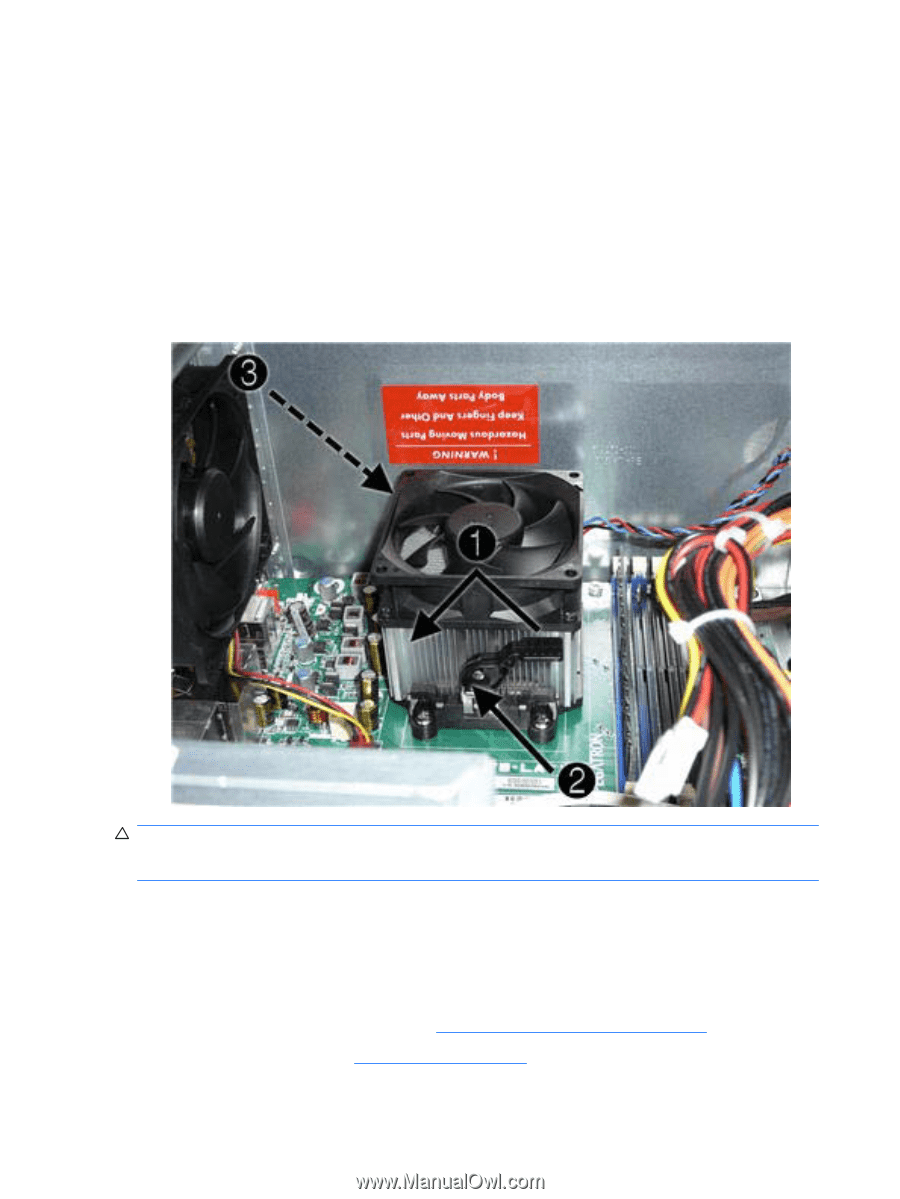
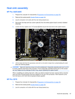
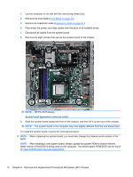
4. Disconnect the heat sink fan control cable from the white system board connector labeled CPU_FAN. 5. Lift the lever (1) that secures the heat sink latch to the heat sink bracket attached to the system board. 6. After loosening the lever, press downward on the lever to release the square clip (2) from the tab on the heat sink bracket. 7. Use the lever to maneuver the square clip on the opposite side on the heat sink (3) free from the tab on the heat sink bracket. 8. Lift the heat sink from the processor and set it on its side to keep from contaminating the work area with thermal grease. CAUTION: Heat sink retaining screws should be tightened in diagonally opposite pairs (as in an X) to evenly seat the heat sink to the processor. This is especially important as the pins on the socket are very fragile and any damage to them may require replacing the system board. When reinstalling an existing heat sink, make sure that its bottom has been cleaned with an alcohol wipe and fresh thermal grease has been applied to the top of the processor. New heatsinks come from the factory with fresh thermal grease already applied. Processor 1. Prepare the computer for disassembly (Preparation for Disassembly on page 32). 2. Remove the access panel (Access Panel on page 33). 68 Chapter 6 Removal and Replacement Procedures Microtower (MT) Chassis
-
 1
1 -
2
-
3
-
4
-
5
-
6
-
7
-
8
-
9
-
10
-
11
-
12
-
13
-
14
-
15
-
16
-
17
-
18
-
19
-
20
-
21
-
22
-
23
-
24
-
25
-
26
-
27
-
28
-
29
-
30
-
31
-
32
-
33
-
34
-
35
-
36
-
37
-
38
-
39
-
40
-
41
-
42
-
43
-
44
-
45
-
46
-
47
-
48
-
49
-
50
-
51
-
52
-
53
-
54
-
55
-
56
-
57
-
58
-
59
-
60
-
61
-
62
-
63
-
64
-
65
-
66
-
67
-
68
-
69
-
70
-
 71
71 -
 72
72 -
 73
73 -
 74
74 -
 75
75 -
 76
76 -
 77
77 -
 78
78 -
 79
79 -
 80
80 -
 81
81 -
82
-
83
-
84
-
85
-
86
-
87
-
88
-
89
-
90
-
91
-
92
-
93
-
94
-
95
-
96
-
97
-
98
-
99
-
100
-
101
-
102
-
103
-
104
-
105
-
106
-
107
-
108
-
109
-
110
-
111
-
112
-
113
-
114
-
115
-
116
-
117
-
118
-
119
-
120
-
121
-
122
-
123
-
124
-
125
-
126
-
127
-
128
-
129
-
130
-
131
-
132
-
133
-
134
-
135
-
136
-
137
-
138
-
139
-
140
 |
 |