HP ProDesk 600 Hardware Reference Guide
HP ProDesk 600 Manual
 |
View all HP ProDesk 600 manuals
Add to My Manuals
Save this manual to your list of manuals |
HP ProDesk 600 manual content summary:
- HP ProDesk 600 | Hardware Reference Guide - Page 1
Hardware Reference Guide HP ProDesk 600 G1 Tower HP ProDesk 600 G1 Small Form Factor - HP ProDesk 600 | Hardware Reference Guide - Page 2
. No part of this document may be photocopied, reproduced, or translated to another language without the prior written consent of Hewlett-Packard Company. Hardware Reference Guide HP ProDesk 600 G1 Tower HP ProDesk 600 G1 Small Form Factor First Edition (April 2013) Document part number: 719015-001 - HP ProDesk 600 | Hardware Reference Guide - Page 3
About This Book This guide provides basic information for upgrading HP ProDesk Business PCs. WARNING! Text set off in this manner indicates that failure to follow directions could result in bodily harm or loss of life. CAUTION: Text set - HP ProDesk 600 | Hardware Reference Guide - Page 4
iv About This Book ENWW - HP ProDesk 600 | Hardware Reference Guide - Page 5
1 Product features ...1 Standard configuration features ...1 Tower (TWR) ...1 Small Form Factor (SFF) ...2 Tower (TWR) front panel components 3 Small Form Factor (SFF) front panel components 4 Tower (TWR) rear panel components 5 Small Form Factor (SFF) rear panel components 6 Media card reader - HP ProDesk 600 | Hardware Reference Guide - Page 6
inch hard drive 41 Installing a security lock ...46 Cable lock ...46 Padlock ...46 HP business PC security lock 47 Front bezel security ...51 3 Small Form Factor (SFF) hardware upgrades 53 Serviceability features ...53 Warnings and cautions ...53 Removing the computer access panel 54 Replacing - HP ProDesk 600 | Hardware Reference Guide - Page 7
Padlock ...87 HP business PC security lock 88 Front bezel security ...92 Appendix A Battery replacement ...94 Appendix B Unlocking the Smart Cover Lock 97 Smart Cover FailSafe Key ...97 Using the - HP ProDesk 600 | Hardware Reference Guide - Page 8
viii ENWW - HP ProDesk 600 | Hardware Reference Guide - Page 9
hardware and software installed in the computer, run the diagnostic utility (included on some computer models only). NOTE: Both computer models can be used in a tower orientation or a desktop orientation. Tower (TWR) ENWW Standard configuration features 1 - HP ProDesk 600 | Hardware Reference Guide - Page 10
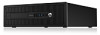
Small Form Factor (SFF) 2 Chapter 1 Product features ENWW - HP ProDesk 600 | Hardware Reference Guide - Page 11
in the Windows taskbar. NOTE: The Power On Light is normally white when the power is on. If it is flashing red, there is a problem with the computer and it is displaying a diagnostic code. Refer to the Maintenance and Service Guide to interpret the code. ENWW Tower (TWR) front panel components 3 - HP ProDesk 600 | Hardware Reference Guide - Page 12
Small Form Factor (SFF) front panel components Drive configuration may vary by model. Some models have a bezel blank covering one or more drive bays. 1 Slim Optical Drive (optional) 5 Headphone Connector 2 USB 2.0 Ports (black) 6 Dual-State Power Button 3 USB 3.0 Ports (blue) 7 Hard Drive - HP ProDesk 600 | Hardware Reference Guide - Page 13
Connector 11 Line-In Audio Connector (blue) 6 USB 3.0 Ports (blue) NOTE: An optional second serial port and an optional parallel port are available from HP. When a device is plugged into the blue can be disabled by changing settings in Computer Setup. ENWW Tower (TWR) rear panel components 5 - HP ProDesk 600 | Hardware Reference Guide - Page 14
Small Form Factor (SFF) rear panel components 1 PS/2 Mouse Connector (green) 7 PS/2 Keyboard Connector (purple) 2 RJ-45 Network Connector 8 DisplayPort Monitor Connectors 3 Serial Connector 4 USB 2.0 Ports (black) 9 VGA Monitor Connector 10 USB 3.0 Ports (blue) 5 Line-In Audio - HP ProDesk 600 | Hardware Reference Guide - Page 15
Duo ● Memory Stick (MS) ● Memory Stick MagicGate ● Memory Stick Select ● Memory Stick Duo ● Memory Stick PRO (MS Duo) (MS PRO) ● Memory Stick PRO Duo (MS PRO Duo) ● Secure Digital Extended Capacity Memory Card (SDXC) ● MicroDrive ● Memory Stick MagicGate Duo ● Memory Stick PROHG Duo ENWW - HP ProDesk 600 | Hardware Reference Guide - Page 16
Play/pause 4 Stop 5 Fast forward Component 6 Mute volume 7 Decrease volume 8 Increase volume 9 Windows logo key 10 Function Using the Windows i k Windows 8 Displays the Start screen Opens charms Displays the Desktop Opens Windows Explorer Goes to files in Search charm Launches Find Computer - HP ProDesk 600 | Hardware Reference Guide - Page 17
arrow or right Moves a window from one monitor to arrow another Moves a window from one monitor to another , (comma) Peeks at the desktop . (period) Snap a metro application to the right Shift + . (period) Snap a metro application to the left Enter Launches Narrator Esc Exits Magnifier - HP ProDesk 600 | Hardware Reference Guide - Page 18
Minimizes non-active desktop windows Break Displays System Properties PgUp PgDn Windows 8 Zooms out (Magnifier) Minimizes non-active desktop windows Displays System use when contacting customer service for assistance. Tower (TWR) Small Form Factor (SFF) 10 Chapter 1 Product features ENWW - HP ProDesk 600 | Hardware Reference Guide - Page 19
service. No tools are needed for most of the installation procedures described in this chapter. Warnings and cautions Before performing upgrades be sure to carefully read all of the applicable instructions, cautions, and warnings in this guide This guide is located on the Web at http://www.hp.com/ - HP ProDesk 600 | Hardware Reference Guide - Page 20
that prohibit opening the computer. 2. Remove all removable media, such as compact discs or USB flash drives, from the computer. 3. Turn off the computer properly through the operating system, (1) then lift the access panel off the computer (2). 12 Chapter 2 Tower (TWR) hardware upgrades ENWW - HP ProDesk 600 | Hardware Reference Guide - Page 21
Replacing the computer access panel Slide the lip on the front end of the access panel under the lip on the front of the chassis (1) then press the back end of the access panel onto the unit so that it locks into place (2). ENWW Replacing the computer access panel 13 - HP ProDesk 600 | Hardware Reference Guide - Page 22
that prohibit opening the computer. 2. Remove all removable media, such as compact discs or USB flash drives, from the computer. 3. Turn off the computer properly through the operating system, the bezel (1), then rotate the bezel off the chassis (2). 14 Chapter 2 Tower (TWR) hardware upgrades ENWW - HP ProDesk 600 | Hardware Reference Guide - Page 23
front bezel (2). NOTE: After removing the 5.25-inch drive bezel blank and installing a drive, you can install an optional bezel trim piece (available from HP) that surrounds the front of the drive. ● To remove a 3.5-inch bezel blank, press outward on the two retaining tabs that hold the bezel blank - HP ProDesk 600 | Hardware Reference Guide - Page 24
blank and installing a slim optical drive, you can install an optional bezel trim piece (available from HP) that surrounds the front of the slim optical drive. Replacing the front bezel Insert the three hooks the chassis (2) and snap it into place. 16 Chapter 2 Tower (TWR) hardware upgrades ENWW - HP ProDesk 600 | Hardware Reference Guide - Page 25
A) 11 DIMM2 (Channel B) 12 DIMM1 (Channel B) 13 Power 14 Power 15 USB 3.0 16 SATA 3.0 17 SATA 3.0 System Board Label X1PCIEXP3 X1PCIEXP2 X1PCIEXP1 X16PCIEXP PAR Memory Module Memory Module Memory Module SATA Drives System Board Front USB 3.0 Ports Primary Hard Drive Any SATA Device other than the - HP ProDesk 600 | Hardware Reference Guide - Page 26
SATA2 light blue 20 USB 2.0 MEDIA black Component Any SATA Device other than the Primary Hard Drive USB 2.0 Device, such populated with at least one preinstalled DIMM. To achieve the maximum memory support, you can populate the system board with up to 32-GB 2 Tower (TWR) hardware upgrades ENWW - HP ProDesk 600 | Hardware Reference Guide - Page 27
the module. 1. Remove/disengage any security devices that prohibit opening the computer. 2. Remove all removable media, such as compact discs or USB flash drives, from the computer. 3. Turn off the computer properly through the operating system, then turn off any external devices. 4. Disconnect - HP ProDesk 600 | Hardware Reference Guide - Page 28
disengaged when the access panel was removed. The computer should automatically recognize the additional memory the next time you turn on the computer. 20 Chapter 2 Tower (TWR) hardware upgrades ENWW - HP ProDesk 600 | Hardware Reference Guide - Page 29
expansion card: 1. Remove/disengage any security devices that prohibit opening the computer. 2. Remove all removable media, such as compact discs or USB flash drives, from the computer. 3. Turn off the computer properly through the operating system, then turn off any external devices. 4. Disconnect - HP ProDesk 600 | Hardware Reference Guide - Page 30
pull free from the socket. Lift the card straight up to remove it. Be sure not to scrape the card against other components. 22 Chapter 2 Tower (TWR) hardware upgrades ENWW - HP ProDesk 600 | Hardware Reference Guide - Page 31
c. If you are removing a PCI Express x16 card, pull the retention arm on the back of the expansion socket away from the card and carefully rock the card back and forth until the connectors pull free from the socket. Lift the card straight up to remove it. Be sure not to scrape the card against other - HP ProDesk 600 | Hardware Reference Guide - Page 32
the computer. 16. Lock any security devices that were disengaged when the computer access panel was removed. 17. Reconfigure the computer, if necessary. 24 Chapter 2 Tower (TWR) hardware upgrades ENWW - HP ProDesk 600 | Hardware Reference Guide - Page 33
Drive positions 1 5.25-inch half-height drive bay 2 Slim optical drive bay 3 3.5-inch drive bay for optional drive (such as a media card reader) 4 Primary 3.5-inch internal hard drive bay 5 Secondary 3.5-inch internal hard drive bay 6 Secondary 2.5-inch internal hard drive bay NOTE: The drive - HP ProDesk 600 | Hardware Reference Guide - Page 34
remove the guide screws from the old drive and install them in the new drive. No. Guide Screw 1 Silver Standard 6-32 Guide Screws 2 Silver and Blue 6-32 Isolation Mounting Screws Device USB 3.0 Media Card Reader Secondary Hard Drive in 3.5-inch Hard Drive Bay 26 Chapter 2 Tower (TWR) hardware - HP ProDesk 600 | Hardware Reference Guide - Page 35
CAUTION: To prevent loss of work and damage to the computer or drive: If you are inserting or removing a drive, shut down the operating system properly, turn off the computer, and unplug the power cord. Do not remove a drive while the computer is on or in standby mode. Before handling a drive, - HP ProDesk 600 | Hardware Reference Guide - Page 36
Removing a 5.25-inch drive NOTE: HP does not offer a 5.25-inch opening the computer. 2. Remove all removable media, such as compact discs or USB flash drives, from the computer. 3. Turn off the computer properly through the damaging the cable. 28 Chapter 2 Tower (TWR) hardware upgrades ENWW - HP ProDesk 600 | Hardware Reference Guide - Page 37
and slide the drive from the drive bay (2). Installing a 5.25-inch drive NOTE: HP does not offer a 5.25-inch optical drive for this computer model. A 5.25 computer. 2. Remove all removable media, such as compact discs or USB flash drives, from the computer. 3. Turn off the computer properly through - HP ProDesk 600 | Hardware Reference Guide - Page 38
. CAUTION: Use only 5-mm long screws as guide screws. Longer screws can damage the internal components of the drive. 8. Slide the drive into the drive bay, making sure to align the guide screws with the guide slots, until the drive snaps into place. 30 Chapter 2 Tower (TWR) hardware upgrades ENWW - HP ProDesk 600 | Hardware Reference Guide - Page 39
drive connectors. 11. Replace the front bezel. NOTE: An optional bezel trim piece that surrounds the front of the 5.25-inch drive is available from HP. Install the bezel trim piece in the front bezel before replacing the front bezel. 12. Replace the computer access panel. 13. Reconnect the power - HP ProDesk 600 | Hardware Reference Guide - Page 40
opening the computer. 2. Remove all removable media, such as compact discs or USB flash drives, from the computer. 3. Turn off the computer properly through the are removing a media card reader, disconnect the USB cable from the system board as indicated in the following illustration. 32 Chapter - HP ProDesk 600 | Hardware Reference Guide - Page 41
7. Press the release lever at the rear of the drive away from the drive (1) and slide the drive from the drive bay (2). ENWW Installing and removing drives 33 - HP ProDesk 600 | Hardware Reference Guide - Page 42
USB HP has supplied four extra 6-32 guide screws on top of the drive cage. Refer to Installing and removing drives on page 69 for an illustration of the extra guide screws location. When replacing a drive, transfer the four 6-32 guide screws from the old drive to the new one. 34 Chapter 2 Tower - HP ProDesk 600 | Hardware Reference Guide - Page 43
bay, making sure to align the guide screws with the guide slots, until the drive snaps into place. 9. If installing a USB 3.0 media card reader, you must use the USB 3.0 to USB 2.0 adapter and connect the adapter cable from the media card reader to the USB 2.0 connector on the system board labeled - HP ProDesk 600 | Hardware Reference Guide - Page 44
devices that prohibit opening the computer. 2. Remove all removable media, such as compact discs or USB flash drives, from the computer. 3. Turn off the computer properly through the operating system, of the cable itself to avoid damaging the cable. 36 Chapter 2 Tower (TWR) hardware upgrades ENWW - HP ProDesk 600 | Hardware Reference Guide - Page 45
optical drive 1. Remove/disengage any security devices that prohibit opening the computer. 2. Remove all removable media, such as compact discs or USB flash drives, from the computer. 3. Turn off the computer properly through the operating system, then turn off any external devices. 4. Disconnect - HP ProDesk 600 | Hardware Reference Guide - Page 46
d. Insert the second pin, and press the entire release latch firmly to fasten the latch securely to the optical drive. 8. Slide the optical drive through the front bezel all the way into the bay so that it locks in place. 38 Chapter 2 Tower (TWR) hardware upgrades ENWW - HP ProDesk 600 | Hardware Reference Guide - Page 47
drive connectors. 11. Replace the front bezel. NOTE: An optional bezel trim piece that surrounds the front of the slim optical drive is available from HP. Install the bezel trim piece in the front bezel before replacing the front bezel. 12. Replace the computer access panel. 13. Reconnect the power - HP ProDesk 600 | Hardware Reference Guide - Page 48
devices that prohibit opening the computer. 2. Remove all removable media, such as compact discs or USB flash drives, from the computer. 3. Turn off the computer properly through the operating system, data cable (2) from the back of the hard drive. 40 Chapter 2 Tower (TWR) hardware upgrades ENWW - HP ProDesk 600 | Hardware Reference Guide - Page 49
from the drive (1) and sliding the drive out of the bay (2). 8. Remove the four guide screws (two on each side) from the old drive. You will need these screws to computer. 2. Remove all removable media, such as compact discs or USB flash drives, from the computer. 3. Turn off the computer properly - HP ProDesk 600 | Hardware Reference Guide - Page 50
screws for 3.5-inch hard drives are installed on the exterior of the hard drive bays. Extra guide screws for 2.5-inch hard drives are not provided on the chassis but can be purchased from HP. Refer to Installing and removing drives on page 26 for an illustration of the extra 6-32 isolation mounting - HP ProDesk 600 | Hardware Reference Guide - Page 51
● You can also install a 2.5-inch hard drive into a 3.5-inch drive bay using an adapter bracket similar to the example shown below. ◦ Slide the drive into the bay adapter bracket, ensuring the connector on the drive is fully inserted into the connector on the adapter bracket. ◦ Secure the drive to - HP ProDesk 600 | Hardware Reference Guide - Page 52
four 6-32 silver and blue isolation mounting guide screws in the adapter bracket (two on each side of the bracket). 7. Slide the drive into the drive bay, making sure to align the guide screws with the guide slots, until the drive snaps into place. 44 Chapter 2 Tower (TWR) hardware upgrades ENWW - HP ProDesk 600 | Hardware Reference Guide - Page 53
board connector. NOTE: You must connect the primary hard drive data cable to the dark blue connector labeled SATA0 to avoid any hard drive performance problems. If you are adding a second hard drive, connect the data cable to one of the light blue SATA connectors. 10. Replace the computer access - HP ProDesk 600 | Hardware Reference Guide - Page 54
Installing a security lock The security locks displayed below and on the following page can be used to secure the computer. Cable lock Padlock 46 Chapter 2 Tower (TWR) hardware upgrades ENWW - HP ProDesk 600 | Hardware Reference Guide - Page 55
HP business PC security lock 1. Fasten the security cable by looping it around a stationary object. 2. Insert the cable lock into the cable lock slot on the back of - HP ProDesk 600 | Hardware Reference Guide - Page 56
cable through one of the two holes in the bracket (2). Use the hole in the bracket that best secures the peripheral device cable. 48 Chapter 2 Tower (TWR) hardware upgrades ENWW - HP ProDesk 600 | Hardware Reference Guide - Page 57
5. Thread the keyboard and mouse cables through the computer chassis lock. 6. Screw the lock to the chassis in the thumbscrew hole using the screw provided. ENWW Installing a security lock 49 - HP ProDesk 600 | Hardware Reference Guide - Page 58
7. Insert the plug end of the security cable into the lock (1) and push the button in (2) to engage the lock. Use the key provided to disengage the lock. 8. When complete, all devices in your workstation will be secured. 50 Chapter 2 Tower (TWR) hardware upgrades ENWW - HP ProDesk 600 | Hardware Reference Guide - Page 59
be locked in place by installing a security screw provided by HP. To install the security screw: 1. Remove/disengage any security devices that prohibit opening the computer. 2. Remove all removable media, such as compact discs or USB flash drives, from the computer. 3. Turn off the computer properly - HP ProDesk 600 | Hardware Reference Guide - Page 60
. 9. Reconnect the power cord and turn on the computer. 10. Lock any security devices that were disengaged when the access panel was removed. 52 Chapter 2 Tower (TWR) hardware upgrades ENWW - HP ProDesk 600 | Hardware Reference Guide - Page 61
3 Small Form Factor (SFF) hardware upgrades Serviceability features The computer includes features that make it easy to upgrade and service. No important electrical and mechanical safety information. This guide is located on the Web at http://www.hp.com/ergo. WARNING! Energized and moving parts - HP ProDesk 600 | Hardware Reference Guide - Page 62
prohibit opening the computer. 2. Remove all removable media, such as compact discs or USB flash drives, from the computer. 3. Turn off the computer properly through the operating system then lift the access panel off the computer (2). 54 Chapter 3 Small Form Factor (SFF) hardware upgrades ENWW - HP ProDesk 600 | Hardware Reference Guide - Page 63
Replacing the computer access panel Slide the lip on the front end of the access panel under the lip on the front of the chassis (1) then press the back end of the access panel onto the unit so that it locks into place (2). ENWW Replacing the computer access panel 55 - HP ProDesk 600 | Hardware Reference Guide - Page 64
that prohibit opening the computer. 2. Remove all removable media, such as compact discs or USB flash drives, from the computer. 3. Turn off the computer properly through the operating bezel (1), then rotate the bezel off the chassis (2). 56 Chapter 3 Small Form Factor (SFF) hardware upgrades ENWW - HP ProDesk 600 | Hardware Reference Guide - Page 65
it (4). NOTE: After removing the slim optical drive bezel blank and installing a slim optical drive, you can install an optional bezel trim piece (available from HP) that surrounds the front of the slim optical drive. ENWW Removing bezel blanks 57 - HP ProDesk 600 | Hardware Reference Guide - Page 66
Replacing the front bezel Insert the four hooks on the bottom side of the bezel into the rectangular holes on the chassis (1) then rotate the top side of the bezel onto the chassis (2) and snap it into place. 58 Chapter 3 Small Form Factor (SFF) hardware upgrades ENWW - HP ProDesk 600 | Hardware Reference Guide - Page 67
from desktop to tower configuration The Small Form Factor computer can be used in a tower orientation with an optional tower stand that can be purchased from HP. 1. Remove/disengage any security devices that prohibit opening the computer. 2. Remove all removable media, such as compact discs or USB - HP ProDesk 600 | Hardware Reference Guide - Page 68
Lock Hood Sensor Memory Module Memory Module Memory Module Memory Module SATA Drives System Board Front USB 3.0 Ports Primary Hard Drive Any SATA Device other than the Primary Hard Drive Any SATA Device other than the Primary Hard Drive 60 Chapter 3 Small Form Factor (SFF) hardware upgrades ENWW - HP ProDesk 600 | Hardware Reference Guide - Page 69
Label SATA2 Color light blue 20 USB 2.0 MEDIA black Component Any SATA Device other than the Primary Hard Drive USB 2.0 Device, such as a are populated with at least one preinstalled DIMM. To achieve the maximum memory support, you can populate the system board with up to 32-GB of memory - HP ProDesk 600 | Hardware Reference Guide - Page 70
that prohibit opening the computer. 2. Remove all removable media, such as compact discs or USB flash drives, from the computer. 3. Turn off the computer properly through the operating system, to the memory modules or system board. 62 Chapter 3 Small Form Factor (SFF) hardware upgrades ENWW - HP ProDesk 600 | Hardware Reference Guide - Page 71
5. If the computer is on a stand, remove the computer from the stand. 6. Remove the computer access panel. WARNING! To reduce risk of personal injury from hot surfaces, allow the internal system components to cool before touching. 7. Open both latches of the memory module socket (1), and insert the - HP ProDesk 600 | Hardware Reference Guide - Page 72
that prohibit opening the computer. 2. Remove all removable media, such as compact discs or USB flash drives, from the computer. 3. Turn off the computer properly through the operating system, rotating the latch to the open position. 64 Chapter 3 Small Form Factor (SFF) hardware upgrades ENWW - HP ProDesk 600 | Hardware Reference Guide - Page 73
9. Before installing an expansion card, remove the expansion slot cover or the existing expansion card. NOTE: Before removing an installed expansion card, disconnect any cables that may be attached to the expansion card. a. If you are installing an expansion card in a vacant socket, remove the - HP ProDesk 600 | Hardware Reference Guide - Page 74
removing an expansion card, you must replace it with a new card or expansion slot cover for proper cooling of internal components during operation. 66 Chapter 3 Small Form Factor (SFF) hardware upgrades ENWW - HP ProDesk 600 | Hardware Reference Guide - Page 75
12. To install a new expansion card, hold the card just above the expansion socket on the system board then move the card toward the rear of the chassis (1) so that the bracket on the card is aligned with the open slot on the rear of the chassis. Press the card straight down into the expansion - HP ProDesk 600 | Hardware Reference Guide - Page 76
than the drive configuration shown above. To verify the type and size of the storage devices installed in the computer, run Computer Setup. 68 Chapter 3 Small Form Factor (SFF) hardware upgrades ENWW - HP ProDesk 600 | Hardware Reference Guide - Page 77
and SATA3). ● Connect a media card reader USB 3.0 cable with a USB 3.0 to USB 2.0 adapter to the USB 2.0 connector on the system board labeled MEDIA. lock in place. HP has provided four extra 6-32 standard guide screws installed on the top of the drive bay. The 6-32 standard guide screws are required - HP ProDesk 600 | Hardware Reference Guide - Page 78
a drive must be mailed, place the drive in a bubble-pack mailer or other protective packaging and label the package "Fragile: Handle With Care." 70 Chapter 3 Small Form Factor (SFF) hardware upgrades ENWW - HP ProDesk 600 | Hardware Reference Guide - Page 79
the computer. 1. Remove/disengage any security devices that prohibit opening the computer. 2. Remove all removable media, such as compact discs or USB flash drives, from the computer. 3. Turn off the computer properly through the operating system, then turn off any external devices. 4. Disconnect - HP ProDesk 600 | Hardware Reference Guide - Page 80
a media card reader, disconnect the USB cable from the system board as indicated in the following illustration. 9. Press inward on the release lever at the rear of the drive (1) and slide the drive out of the rear of the drive bay (2). 72 Chapter 3 Small Form Factor (SFF) hardware upgrades ENWW - HP ProDesk 600 | Hardware Reference Guide - Page 81
computer. 2. Remove all removable media, such as compact discs or USB flash drives, from the computer. 3. Turn off the computer properly more information. 8. Install 6-32 guide screws in the holes on each side of the drive. NOTE: HP has supplied four extra 6-32 guide screws on top of the drive - HP ProDesk 600 | Hardware Reference Guide - Page 82
9. Rotate the drive cage to its upright position. 10. Slide the drive into the drive bay, making sure to align the guide screws with the guide slots, until the drive snaps into place. 74 Chapter 3 Small Form Factor (SFF) hardware upgrades ENWW - HP ProDesk 600 | Hardware Reference Guide - Page 83
and connect the adapter cable from the media card reader to the USB 2.0 connector on the system board labeled MEDIA. NOTE: Refer to System board connections on page 60 for an illustration of the system board drive connectors. - HP ProDesk 600 | Hardware Reference Guide - Page 84
that prohibit opening the computer. 2. Remove all removable media, such as compact discs or USB flash drives, from the computer. 3. Turn off the computer properly through the operating system, the cable itself to avoid damaging the cable. 76 Chapter 3 Small Form Factor (SFF) hardware upgrades ENWW - HP ProDesk 600 | Hardware Reference Guide - Page 85
optical drive 1. Remove/disengage any security devices that prohibit opening the computer. 2. Remove all removable media, such as compact discs or USB flash drives, from the computer. 3. Turn off the computer properly through the operating system, then turn off any external devices. 4. Disconnect - HP ProDesk 600 | Hardware Reference Guide - Page 86
piece that surrounds the front of the optical drive is available from HP. Install the bezel trim piece in the front bezel before installing the 2. Remove all removable media, such as compact discs or USB flash drives, from the computer. 3. Turn off the Small Form Factor (SFF) hardware upgrades ENWW - HP ProDesk 600 | Hardware Reference Guide - Page 87
5. If the computer is on a stand, remove the computer from the stand. 6. Remove the computer access panel. 7. Disconnect the power cable (1) and data cable (2) from the back of the hard drive. 8. Pull the release lever next to the rear of the hard drive outward (1). While pulling the release lever - HP ProDesk 600 | Hardware Reference Guide - Page 88
isolation mounting guide screws from the old hard drive to the new hard drive. 10. Align the guide screws with the slots on the chassis drive cage, press the hard drive down into the bay, then slide it forward until it stops and locks in place. 80 Chapter 3 Small Form Factor (SFF) hardware upgrades - HP ProDesk 600 | Hardware Reference Guide - Page 89
for the primary hard drive must be connected to the dark blue connector labeled SATA0 on the system board to avoid any hard drive performance problems. 12. Replace the access panel. 13. If the computer was on a stand, replace the stand. 14. Reconnect the power cord and turn on the computer - HP ProDesk 600 | Hardware Reference Guide - Page 90
prohibit opening the computer. 2. Remove all removable media, such as compact discs or USB flash drives, from the computer. 3. Turn off the computer properly through the operating system . 7. Rotate the drive cage to its upright position. 82 Chapter 3 Small Form Factor (SFF) hardware upgrades ENWW - HP ProDesk 600 | Hardware Reference Guide - Page 91
8. Disconnect the power cable (1) and data cable (2) from the back of the hard drive. 9. Pull outward on the release lever at the rear of the drive (1) then slide the drive back until it stops and pull it down and out of the drive bay (2). ENWW Installing and removing drives 83 - HP ProDesk 600 | Hardware Reference Guide - Page 92
discs or USB flash drives, guide screws (two on each side of the drive). NOTE: M3 metric isolation mounting guide screws can be purchased from HP. When replacing a drive, transfer the four M3 isolation mounting guide screws from the old drive to the new one. 84 Chapter 3 Small Form Factor (SFF - HP ProDesk 600 | Hardware Reference Guide - Page 93
8. Rotate the drive cage to its upright position. 9. Align the guide screws on the drive with the J-slots on the sides of the drive bay. Press the drive up into the drive bay then slide it forward until it locks in place. ENWW Installing and removing drives 85 - HP ProDesk 600 | Hardware Reference Guide - Page 94
and any external devices, then turn on the computer. 15. Lock any security devices that were disengaged when the access panel was removed. 86 Chapter 3 Small Form Factor (SFF) hardware upgrades ENWW - HP ProDesk 600 | Hardware Reference Guide - Page 95
Installing a security lock The security locks displayed below and on the following pages can be used to secure the computer. Cable lock Padlock ENWW Installing a security lock 87 - HP ProDesk 600 | Hardware Reference Guide - Page 96
HP business PC security lock 1. Fasten the security cable by looping it around a stationary object. 2. Insert the cable lock into the cable lock inserting the key into the key hole on the rear of the lock and rotating the key 90 degrees. 88 Chapter 3 Small Form Factor (SFF) hardware upgrades ENWW - HP ProDesk 600 | Hardware Reference Guide - Page 97
3. Slide the security cable through the hole in the cable lock on the rear of the monitor. 4. Use the bracket provided in the kit to secure other peripheral devices by laying the device cable across the center of the bracket (1) and inserting the security cable through one of the two holes in the - HP ProDesk 600 | Hardware Reference Guide - Page 98
5. Thread the keyboard and mouse cables through the computer chassis lock. 6. Screw the lock to the chassis in the thumbscrew hole using the screw provided. 90 Chapter 3 Small Form Factor (SFF) hardware upgrades ENWW - HP ProDesk 600 | Hardware Reference Guide - Page 99
7. Insert the plug end of the security cable into the lock (1) and push the button in (2) to engage the lock. Use the key provided to disengage the lock. 8. When complete, all devices in your workstation will be secured. ENWW Installing a security lock 91 - HP ProDesk 600 | Hardware Reference Guide - Page 100
provided by HP. To install the security screw: 1. Remove/disengage any security devices that prohibit opening the computer. 2. Remove all removable media, such as compact discs or USB flash drives, screws located on top of the drive cage. 92 Chapter 3 Small Form Factor (SFF) hardware upgrades ENWW - HP ProDesk 600 | Hardware Reference Guide - Page 101
8. Install the security screw through the middle front bezel release tab to secure the front bezel in place. 9. Replace the access panel. 10. If the computer was on a stand, replace the stand. 11. Reconnect the power cord and turn on the computer. 12. Lock any security devices that were disengaged - HP ProDesk 600 | Hardware Reference Guide - Page 102
or dispose of in fire or water. Replace the battery only with the HP spare designated for this product. CAUTION: Before replacing the battery, it hp.com/ recycle. 1. Remove/disengage any security devices that prohibit opening the computer. 2. Remove all removable media, such as compact discs or USB - HP ProDesk 600 | Hardware Reference Guide - Page 103
7. Depending on the type of battery holder on the system board, complete the following instructions to replace the battery. Type 1 a. Lift the battery out of its holder. b. Slide the replacement battery into position, positive side up. The battery holder automatically - HP ProDesk 600 | Hardware Reference Guide - Page 104
b. Insert the new battery and position the clip back into place. NOTE: After the battery has been replaced, use the following steps to complete this procedure. 8. Replace the computer access panel. 9. Plug in the computer and turn on power to the computer. 10. Reset the date and time, your passwords - HP ProDesk 600 | Hardware Reference Guide - Page 105
of the following circumstances: ● Power outage ● Startup failure ● PC component (for example, processor or power supply) failure ● Forgotten available from HP. Be prepared; order this key before you need it. To obtain a FailSafe Key: ● Contact an authorized HP reseller or service provider. Order - HP ProDesk 600 | Hardware Reference Guide - Page 106
that prohibit opening the computer. 2. Remove all removable media, such as compact discs or USB flash drives, from the computer. 3. Turn off the computer properly through the operating system, . ● Removing the Smart Cover Lock Screws from the Tower 98 Appendix B Unlocking the Smart Cover Lock ENWW - HP ProDesk 600 | Hardware Reference Guide - Page 107
● Removing the Smart Cover Lock Screw from the Small Form Factor 6. You can now remove the access panel. To reattach the Smart Cover Lock, secure the lock in place with the tamper-proof screws. ENWW Using the Smart Cover FailSafe Key to remove the Smart Cover Lock 99 - HP ProDesk 600 | Hardware Reference Guide - Page 108
mat. If you do not have any of the suggested equipment for proper grounding, contact an HP authorized dealer, reseller, or service provider. NOTE: For more information on static electricity, contact an HP authorized dealer, reseller, or service provider. 100 Appendix C Electrostatic discharge ENWW - HP ProDesk 600 | Hardware Reference Guide - Page 109
the computer by blocking any vents or air intakes. Do not place the keyboard, with the keyboard feet down, directly against the front of the desktop unit as this also restricts airflow. ● Never operate the computer with the access panel or any of the expansion card slot covers removed. ● Do not - HP ProDesk 600 | Hardware Reference Guide - Page 110
to sudden changes in temperature, as condensation may form inside the unit. If the temperature suddenly changes and have it checked by an authorized HP service provider. Shipping preparation Follow these suggestions files on PD discs, tape cartridges, CDs, or USB flash drives. Be sure that the backup - HP ProDesk 600 | Hardware Reference Guide - Page 111
cable lock 46 TWR front bezel 51 TWR HP Business PC Security Lock 47 TWR padlock 46 M media card reader features 7 SFF installation 73 SFF removal 71 TWR installation 34 TWR removal 32 memory SFF installation 61 SFF socket population 61 SFF specifications 61 TWR installation 18 TWR socket population - HP ProDesk 600 | Hardware Reference Guide - Page 112
lock 46 TWR front bezel 51 TWR HP Business PC Security Lock 47 TWR padlock 46 serial number locations 10 shipping preparation 102 Smart Cover Lock 97 specifications SFF memory 61 TWR memory 18 system board connections SFF 60 TWR 17 T tower conversion SFF 59 U unlocking access panel 97 V ventilation
-
 1
1 -
 2
2 -
 3
3 -
 4
4 -
 5
5 -
 6
6 -
 7
7 -
8
-
9
-
10
-
11
-
12
-
13
-
14
-
15
-
16
-
17
-
18
-
19
-
20
-
21
-
22
-
23
-
24
-
25
-
26
-
27
-
28
-
29
-
30
-
31
-
32
-
33
-
34
-
35
-
36
-
37
-
38
-
39
-
40
-
41
-
42
-
43
-
44
-
45
-
46
-
47
-
48
-
49
-
50
-
51
-
52
-
53
-
54
-
55
-
56
-
57
-
58
-
59
-
60
-
61
-
62
-
63
-
64
-
65
-
66
-
67
-
68
-
69
-
70
-
71
-
72
-
73
-
74
-
75
-
76
-
77
-
78
-
79
-
80
-
81
-
82
-
83
-
84
-
85
-
86
-
87
-
88
-
89
-
90
-
91
-
92
-
93
-
94
-
95
-
96
-
97
-
98
-
99
-
100
-
101
-
102
-
103
-
104
-
105
-
106
-
107
-
108
-
109
-
110
-
111
-
112
 |
 |

Hardware Reference Guide
HP ProDesk 600 G1 Tower
HP ProDesk 600 G1 Small Form Factor