HP ProDesk 600 Hardware Reference Guide - Page 34
Installing and removing drives
 |
View all HP ProDesk 600 manuals
Add to My Manuals
Save this manual to your list of manuals |
Page 34 highlights
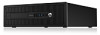
Installing and removing drives When installing drives, follow these guidelines: ● The primary Serial ATA (SATA) hard drive must be connected to the dark blue primary SATA connector on the system board labeled SATA0. ● Connect secondary hard drives and optical drives to any of the light blue SATA connectors on the system board (labeled SATA1, SATA2, and SATA3). ● Connect a media card reader USB 3.0 cable with a USB 3.0 to USB 2.0 adapter to the USB 2.0 connector on the system board labeled MEDIA. ● The power cable for the drives has two branches coming off the system board connector. The first branch is a three-headed cable with the first connector routed to the 5.25-inch bay, the second connector routed to the 3.5-inch bay, and the third (two-wire) connector routed to the slim optical drive bay. The second branch is a three-headed cable with the first connector routed to the bottom 2.5-inch hard drive bay, the second connector routed to the middle 3.5-inch hard drive bay, and the third connector routed to the top 3.5-inch hard drive bay. ● You must install guide screws to ensure the drive will line up correctly in the drive cage and lock in place. HP has provided extra guide screws (four 6-32 silver and blue isolation mounting guide screws and four silver 6-32 standard guide screws) installed on the side of the drive bays. The 6-32 isolation mounting screws are required for 3.5-inch hard drives installed in the 3.5-inch hard drive bays. The 6-32 standard guide screws are required for a USB 3.0 media card reader installed in the 3.5-inch optional drive bay. M3 metric guide screws for 5.25-inch optical drives and M3 isolation mounting guide screws for 2.5-inch hard drives are not provided. If you are replacing a drive, remove the guide screws from the old drive and install them in the new drive. No. Guide Screw 1 Silver Standard 6-32 Guide Screws 2 Silver and Blue 6-32 Isolation Mounting Screws Device USB 3.0 Media Card Reader Secondary Hard Drive in 3.5-inch Hard Drive Bay 26 Chapter 2 Tower (TWR) hardware upgrades ENWW
-
 1
1 -
2
-
3
-
4
-
5
-
6
-
7
-
8
-
9
-
10
-
11
-
12
-
13
-
14
-
15
-
16
-
17
-
18
-
19
-
20
-
21
-
22
-
23
-
24
-
25
-
26
-
27
-
28
-
 29
29 -
 30
30 -
 31
31 -
 32
32 -
 33
33 -
 34
34 -
 35
35 -
 36
36 -
 37
37 -
 38
38 -
 39
39 -
40
-
41
-
42
-
43
-
44
-
45
-
46
-
47
-
48
-
49
-
50
-
51
-
52
-
53
-
54
-
55
-
56
-
57
-
58
-
59
-
60
-
61
-
62
-
63
-
64
-
65
-
66
-
67
-
68
-
69
-
70
-
71
-
72
-
73
-
74
-
75
-
76
-
77
-
78
-
79
-
80
-
81
-
82
-
83
-
84
-
85
-
86
-
87
-
88
-
89
-
90
-
91
-
92
-
93
-
94
-
95
-
96
-
97
-
98
-
99
-
100
-
101
-
102
-
103
-
104
-
105
-
106
-
107
-
108
-
109
-
110
-
111
-
112
 |
 |
