HP Scitex FB10000 Geffen TS Error 67019 - Page 4
HP Scitex FB10000 Manual
 |
View all HP Scitex FB10000 manuals
Add to My Manuals
Save this manual to your list of manuals |
Page 4 highlights
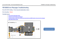
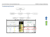
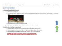
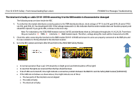
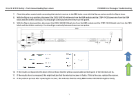
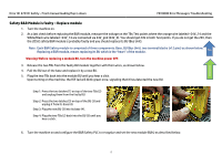
Error ID: 67019: Safety - Front manual loading flap is down FB10000 Error Messages Troubleshooting The interlock is faulty or cable CX161-03540 connecting it to the B&R module is disconnected or damaged The following steps are done inside the REC. 4. To verify that the module distributes correctly pulses to the TBM distribution block, check voltage of TP 15 via 24V_gnd (24V_0) and of TP25 via 24V_gnd (24V_0). You should get 8-20V. If the voltage measured is 0, this indicates that the entire module does not function properly and should be replaced. If you get 8-20V, continue to the next step. Note: For redundancy, the 2SDI2 B&R module receives 24V DC and distributes them as 24V pulses through pins 15,16,25,26. From there they are routed to: TBMs interlocks B&R module inputs. Therefore, voltage along this route will be measured as 8-20V. 5. Check the cable connecting the interlock to the B&R module [CX161-03540] and ensure its wires are properly connected to the B&R pins and its coax connector is firmly attached to the interlock receiver. 6. Go to the REC cabinet and check LEDs SI9 and S20 in the 2SDI2 B&R Safety Module. Top Flowchart • In normal operation (flap is up), S19 should be on (light green) and S20 should be off (no light) • In case that the lights are reversed then the flap should be down. • If all of LEDs are turned off, this might indicate a connection problem between the B&R PLC and the Safety B&R module [X20SI9100]. • If the LEDS do not behave as shown above, this might indicate one of three: o The two parts of the interlock are not aligned o The cable is faulty o The interlock is faulty.
-
 1
1 -
 2
2 -
 3
3 -
 4
4 -
 5
5 -
 6
6 -
 7
7
 |
 |
