HP Scitex FB10000 Geffen TS Error 67019 - Page 6
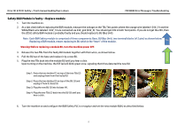
Safety B&R Module is faulty - Replace module, Warning! Before replacing a module BU
 |
View all HP Scitex FB10000 manuals
Add to My Manuals
Save this manual to your list of manuals |
Page 6 highlights
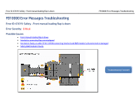
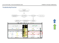
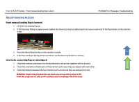
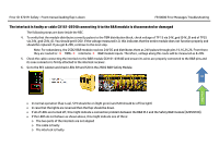
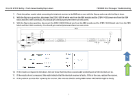
Error ID: 67019: Safety - Front manual loading flap is down FB10000 Error Messages Troubleshooting Safety B&R Module is faulty - Replace module 1. Turn the machine on. 2. As a last check before replacing the B&R module, measure the voltage on the TBs Test points where the orange wire labeled +24V_14 and the White/Black wire labeled +24V_14 are connected via 24V_gnd (24V_0). You should get 24V in both Test points. If you do not get the 24V, then the 2DSI2 safety B&R module is probably faulty and you should replace its BU (Bus Unit). Note: Each B&R Safety module is comprised of three components: Base, BU (Bus Unit), two terminal blocks (x12 pins) as shown below. Replacing a B&R module, means replacing its BU which is the "heart" of the module. Top Warning! Before replacing a module BU, turn the machine power OFF. Flowchart 3. Release the two TBs from the faulty BU module together with their wires, as shown below. 4. Pull the BU out of the base and replace it by a new BU. 5. Plug the two TBs back into the module BU until you hear a click. Upon turning on the machine, the R/E led will blink green once, signaling that it has detected the new BU. Step 1: Press the two latches (1) on top of the two TBs (2) and unplug them from the faulty BU. Step 2: Press the two latches (5) on top of the BU (3) and unplug it from its base (4). Step 3: Plug the new BU (3) into its base (4). Step 4: Plug the two TBs (2) back into the BU (3) until you hear a click. 6. Turn the machine on and configure the B&R Safety PLC to recognize and set the new module BU(s) as described below. 2
-
 1
1 -
 2
2 -
 3
3 -
 4
4 -
 5
5 -
 6
6 -
 7
7
 |
 |
