HP Scitex FB7500 User Instructions Replacing a Print Head - Page 8
The print head 26-pin connector has a notch. This notch
 |
View all HP Scitex FB7500 manuals
Add to My Manuals
Save this manual to your list of manuals |
Page 8 highlights
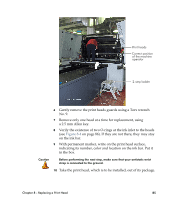
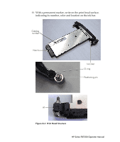
16 Wrap the print head connector with the protective polyethylene strip, as shown in Figure 8-7 (supplied in the Accessories Kit). Protective strip is used to protect print head electronic parts from ink contamination whenever performing print head replacement or maintenance. Protective strip Figure 8-7 Protective Polyethylene Strip 17 Before inserting the print head, verify that it is correctly oriented, as follows: • Catalog number is facing up on a legible and clear label: PZFXXXXXX-XX-RXXCXX. • The print head 26-pin connector has a notch. This notch should face upward when inserting it into the slot, otherwise the 26-pin connector will not fit the PIC connector. • The print head is connected to the ink bar with two screws. These screws look identical, but the left one is marked as "A1" (see Figure 8-4 on page 86) and serves for precise positioning of the print head. HP Scitex FB7500 Operator Manual
-
 1
1 -
2
-
 3
3 -
 4
4 -
 5
5 -
 6
6 -
 7
7 -
 8
8 -
 9
9 -
 10
10
 |
 |
