HP Scitex FB7500 User Instructions Replacing a Print Head - Page 9
Print head location
 |
View all HP Scitex FB7500 manuals
Add to My Manuals
Save this manual to your list of manuals |
Page 9 highlights
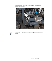
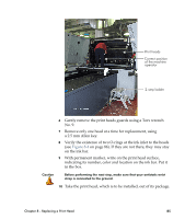
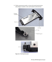
18 Hold the print head parallel to the ink bar and carefully insert it into its slot (with the protective strip). When the head is almost inside, hold the first screw with one hand and with your other hand pull the strip out. Then hold the second screw with this hand and continue to insert the head until its connector reaches the connector on the PIC board. 19 When you feel that the head's connector is fixed properly to the PIC's connector, turn the first screw 2 turns, then turn the second screw 2 turns. Note Do not tighten the first screw leaving the second screw open. This may course bending of the head's connector and damage to the pins. 20 Repeat step 18 until the ink input surface touches the ink bar surface and the print head is perfectly fixed in its place. 21 Turn the A1 bolt using a Torque meter 0.6 N/m and only then turn the right screw. 22 Repeat steps 10 - 18 for the other print heads to be replaced. 23 Document the Heads Signature printout before removal in the "Heads Dismantling Form" along with the following data: • Print head catalog number • Machine number • Print head location • Date of installation • Date of removal • Reason for replacement • Ink batch number • Name of the machine operator 24 Gently return the print heads guards using a Torx wrench No. 9. 25 Lower the printing bridge. 26 Open the taps on the secondary ink tanks. 27 Connect the fume extraction duct to the extraction pipe (see Figure 8-2 on page 83). Chapter 8 - Replacing a Print Head 89
-
 1
1 -
2
-
3
-
 4
4 -
 5
5 -
 6
6 -
 7
7 -
 8
8 -
 9
9 -
 10
10
 |
 |
