HP Spectre XT Ultrabook 13-2100 HP SpectreXT Maintenance and Service Guide - Page 48
USB/Audio see, USB/Audio board
 |
View all HP Spectre XT Ultrabook 13-2100 manuals
Add to My Manuals
Save this manual to your list of manuals |
Page 48 highlights
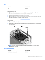
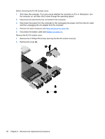
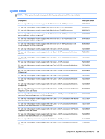
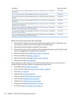
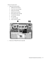
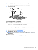
Description For use only with computer models equipped with Intel Core i7-3537U processor for Windows 8 Professional For use only with computer models equipped with Intel Core i7-3337U processor For use only with computer models equipped with Intel Core i7-3337U processor for Windows 8 Standard For use only with computer models equipped with Intel Core i7-3337U processor for Windows 8 Professional For use only with computer models equipped with Intel Core i7-3537U processor in the People's Republic of China and Russia For use only with computer models equipped with Intel Core i7-3537U processor for Windows 8 Standard in the People's Republic of China and Russia For use only with computer models equipped with Intel Core i7-3337U processor in the People's Republic of China and Russia For use only with computer models equipped with Intel Core i7-3337U processor for Windows 8 Standard in the People's Republic of China and Russia Spare part number 714758-601 714759-001 714759-501 714759-601 714760-001 714760-501 714761-001 714761-501 Before removing the system board, follow these steps: 1. Shut down the computer. If you are unsure whether the computer is off or in Hibernation, turn the computer on, and then shut it down through the operating system. 2. Disconnect all external devices connected to the computer. 3. Disconnect the power from the computer by first unplugging the power cord from the AC outlet and then unplugging the AC adapter from the computer. 4. Remove the base enclosure (see Base enclosure on page 29). 5. Remove the battery (see Battery on page 31). 6. Remove the WLAN module (see WLAN module on page 36). 7. Remove the fan (see Fan on page 37). When replacing the system board, be sure that the following components are removed from the defective system board and installed on the replacement system board: ● RTC battery (see RTC battery on page 33) ● Power connector cable (see Power connector cable on page 50) ● Fan (see Fan on page 37). ● Heat sink (see Heat sink on page 43) ● WLAN module see (WLAN module on page 36). ● Hard drive (see Solid-state drive on page 35). ● USB/Audio (see USB/Audio board on page 46), ● Display panel cable (see Display panel on page 54). ● RJ-45 cover (see RJ-45 module cover on page 37). 40 Chapter 4 Removal and replacement procedures
-
 1
1 -
2
-
3
-
4
-
5
-
6
-
7
-
8
-
9
-
10
-
11
-
12
-
13
-
14
-
15
-
16
-
17
-
18
-
19
-
20
-
21
-
22
-
23
-
24
-
25
-
26
-
27
-
28
-
29
-
30
-
31
-
32
-
33
-
34
-
35
-
36
-
37
-
38
-
39
-
40
-
41
-
42
-
 43
43 -
 44
44 -
 45
45 -
 46
46 -
 47
47 -
 48
48 -
 49
49 -
 50
50 -
 51
51 -
 52
52 -
 53
53 -
54
-
55
-
56
-
57
-
58
-
59
-
60
-
61
-
62
-
63
-
64
-
65
-
66
-
67
-
68
-
69
-
70
-
71
-
72
-
73
-
74
-
75
-
76
-
77
-
78
-
79
-
80
-
81
-
82
-
83
-
84
-
85
-
86
-
87
-
88
-
89
-
90
 |
 |