HP Spectre XT Ultrabook 13-2100 HP SpectreXT Maintenance and Service Guide - Page 65
Remove the panel cable from the clips on the left edge, and then loosen the cable from
 |
View all HP Spectre XT Ultrabook 13-2100 manuals
Add to My Manuals
Save this manual to your list of manuals |
Page 65 highlights
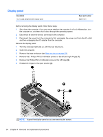
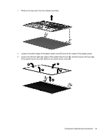
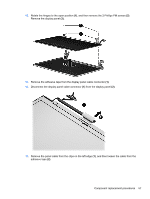
12. Rotate the hinges to the open position (1), and then remove the 2 Phillips PM screws (2). Remove the display panel (3). 13. Remove the adhesive tape from the display panel cable connector (1). 14. Disconnect the display panel cable connector (1) from the display panel (2). 15. Remove the panel cable from the clips on the left edge (1), and then loosen the cable from the adhesive tape (2). Component replacement procedures 57
-
 1
1 -
2
-
3
-
4
-
5
-
6
-
7
-
8
-
9
-
10
-
11
-
12
-
13
-
14
-
15
-
16
-
17
-
18
-
19
-
20
-
21
-
22
-
23
-
24
-
25
-
26
-
27
-
28
-
29
-
30
-
31
-
32
-
33
-
34
-
35
-
36
-
37
-
38
-
39
-
40
-
41
-
42
-
43
-
44
-
45
-
46
-
47
-
48
-
49
-
50
-
51
-
52
-
53
-
54
-
55
-
56
-
57
-
58
-
59
-
 60
60 -
 61
61 -
 62
62 -
 63
63 -
 64
64 -
 65
65 -
 66
66 -
 67
67 -
 68
68 -
 69
69 -
 70
70 -
71
-
72
-
73
-
74
-
75
-
76
-
77
-
78
-
79
-
80
-
81
-
82
-
83
-
84
-
85
-
86
-
87
-
88
-
89
-
90
 |
 |

12.
Rotate the hinges to the open position
(1)
, and then remove the 2 Phillips PM screws
(2)
.
Remove the display panel
(3)
.
13.
Remove the adhesive tape from the display panel cable connector
(1)
.
14.
Disconnect the display panel cable connector
(1)
from the display panel
(2)
.
15.
Remove the panel cable from the clips on the left edge
(1)
, and then loosen the cable from the
adhesive tape
(2)
.
Component replacement procedures
57