HP T5540 Hardware Reference Guide: HP t5145/t5540/t5545/t5630 Thin Clients - Page 12
Installing the Stand
 |
UPC - 884420407706
View all HP T5540 manuals
Add to My Manuals
Save this manual to your list of manuals |
Page 12 highlights
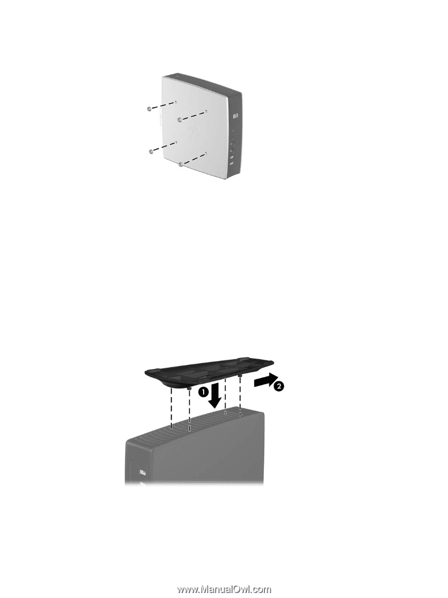
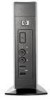
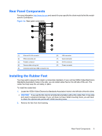
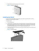
3. Align the feet with their holes and press them in securely. Figure 1-5 Installing the rubber feet Installing the Stand If your unit does not have VESA mounting holes, you will need to use the thin client in a vertical orientation and install the stand for stability. To install the stand: 1. Turn unit upside down. 2. Locate the slots on the bottom of the unit into which the tabs on the stand fit. Position the stand with the wide part toward the front of the unit. Align the tabs on the widest part of the stand with the slots approximately 7.6 cm (3 inches) from the front of the unit and the tabs on the narrower part with the slots approximately 3.8 cm (1.5 inches) from the rear of the unit. 3. Insert the tabs into the slots, then press the stand down and slide it toward the rear of the thin client until it locks into place. Figure 1-6 Installing the stand 6 Chapter 1 Product Features
-
 1
1 -
2
-
3
-
4
-
5
-
6
-
 7
7 -
 8
8 -
 9
9 -
 10
10 -
 11
11 -
 12
12 -
 13
13 -
 14
14 -
 15
15 -
 16
16 -
 17
17 -
18
-
19
-
20
-
21
-
22
-
23
-
24
-
25
-
26
-
27
-
28
-
29
-
30
-
31
-
32
-
33
-
34
-
35
-
36
-
37
-
38
-
39
 |
 |