HP T5540 Hardware Reference Guide: HP t5145/t5540/t5545/t5630 Thin Clients - Page 22
Installing Thin Client Options, Installing the USB Device
 |
UPC - 884420407706
View all HP T5540 manuals
Add to My Manuals
Save this manual to your list of manuals |
Page 22 highlights
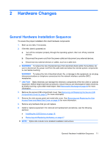
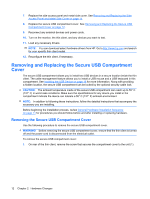
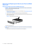
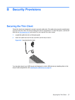
Installing Thin Client Options Various options can be installed on the thin client: ● Installing the USB Device on page 16 ● Removing and Replacing the Battery on page 17 Installing the USB Device Before beginning the replacement process, review General Hardware Installation Sequence on page 11 for procedures you should follow before and after installing or replacing hardware. ▲ Insert the USB device into the USB port in the secure USB compartment. See the following illustration for the location of the ports in the secure USB compartment. Figure 2-6 USB ports in the secure USB compartment If you install a USB mouse and a USB keyboard in the secure USB compartment, route the cables around and through the clips, then out the secure cable routing slot, as shown in the following illustration. Figure 2-7 Using the secure cable routing slot 16 Chapter 2 Hardware Changes
-
 1
1 -
2
-
3
-
4
-
5
-
6
-
7
-
8
-
9
-
10
-
11
-
12
-
13
-
14
-
15
-
16
-
 17
17 -
 18
18 -
 19
19 -
 20
20 -
 21
21 -
 22
22 -
 23
23 -
 24
24 -
 25
25 -
 26
26 -
 27
27 -
28
-
29
-
30
-
31
-
32
-
33
-
34
-
35
-
36
-
37
-
38
-
39
 |
 |