HP TC1000 Maintenance and Service Guide, Compaq Tablet PC TC1000 - Page 95
Removing the Mini PCI Communications Board, Mini PCI Communications Board
 |
UPC - 613326724071
View all HP TC1000 manuals
Add to My Manuals
Save this manual to your list of manuals |
Page 95 highlights
Removal and Replacement Procedures e. Disconnect the modem cable 1 and the two antenna cables 2 from the mini PCI communications board (Figure 5-4). f. Spread the retaining tabs 3 securing the mini PCI communications board to the system board. g. The mini PCI communications board will rise up at a 45-degree angle. h. Pull the mini PCI communications board away from the connector at a 45-degree angle 4. Figure 5-4. Removing the Mini PCI Communications Board Mini PCI Communications Board Spare Part Number Information Mini PCI Type III wireless local area network (LAN) card 310670-001 Reverse the preceding procedures to install the mini PCI communications board. Maintenance and Service Guide 5-7
-
 1
1 -
2
-
3
-
4
-
5
-
6
-
7
-
8
-
9
-
10
-
11
-
12
-
13
-
14
-
15
-
16
-
17
-
18
-
19
-
20
-
21
-
22
-
23
-
24
-
25
-
26
-
27
-
28
-
29
-
30
-
31
-
32
-
33
-
34
-
35
-
36
-
37
-
38
-
39
-
40
-
41
-
42
-
43
-
44
-
45
-
46
-
47
-
48
-
49
-
50
-
51
-
52
-
53
-
54
-
55
-
56
-
57
-
58
-
59
-
60
-
61
-
62
-
63
-
64
-
65
-
66
-
67
-
68
-
69
-
70
-
71
-
72
-
73
-
74
-
75
-
76
-
77
-
78
-
79
-
80
-
81
-
82
-
83
-
84
-
85
-
86
-
87
-
88
-
89
-
 90
90 -
 91
91 -
 92
92 -
 93
93 -
 94
94 -
 95
95 -
 96
96 -
 97
97 -
 98
98 -
 99
99 -
 100
100 -
101
-
102
-
103
-
104
-
105
-
106
-
107
-
108
-
109
-
110
-
111
-
112
-
113
-
114
-
115
-
116
-
117
-
118
-
119
-
120
-
121
-
122
-
123
-
124
-
125
-
126
-
127
-
128
-
129
-
130
-
131
-
132
-
133
-
134
-
135
-
136
-
137
-
138
-
139
-
140
-
141
-
142
-
143
-
144
-
145
-
146
-
147
-
148
-
149
-
150
-
151
-
152
-
153
-
154
-
155
-
156
-
157
-
158
-
159
-
160
-
161
-
162
-
163
-
164
-
165
-
166
-
167
-
168
-
169
-
170
-
171
-
172
-
173
-
174
-
175
 |
 |

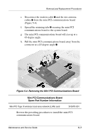
Removal and Replacement Procedures
Maintenance and Service Guide
5–7
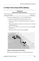
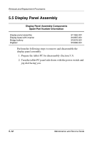
e.
Disconnect the modem cable
1
and the two antenna
cables
2
from the mini PCI communications board
(Figure 5-4).
f.
Spread the retaining tabs
3
securing the mini PCI
communications board to the system board.
g.
The mini PCI communications board will rise up at a
45-degree angle.
h.
Pull the mini PCI communications board away from the
connector at a 45-degree angle
4
.
Figure 5-4. Removing the Mini PCI Communications Board
Reverse the preceding procedures to install the mini PCI
communications board.
Mini PCI Communications Board
Spare Part Number Information
Mini PCI Type III wireless local area network (LAN) card
310670-001