HP TouchSmart tm2t-2100 HP TouchSmart tm2 Notebook PC - Maintenance and Servic - Page 69
CAUTION, Lift the display assembly
 |
View all HP TouchSmart tm2t-2100 manuals
Add to My Manuals
Save this manual to your list of manuals |
Page 69 highlights
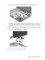
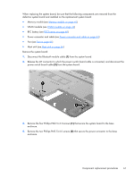
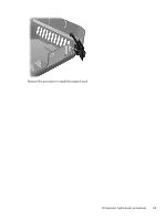
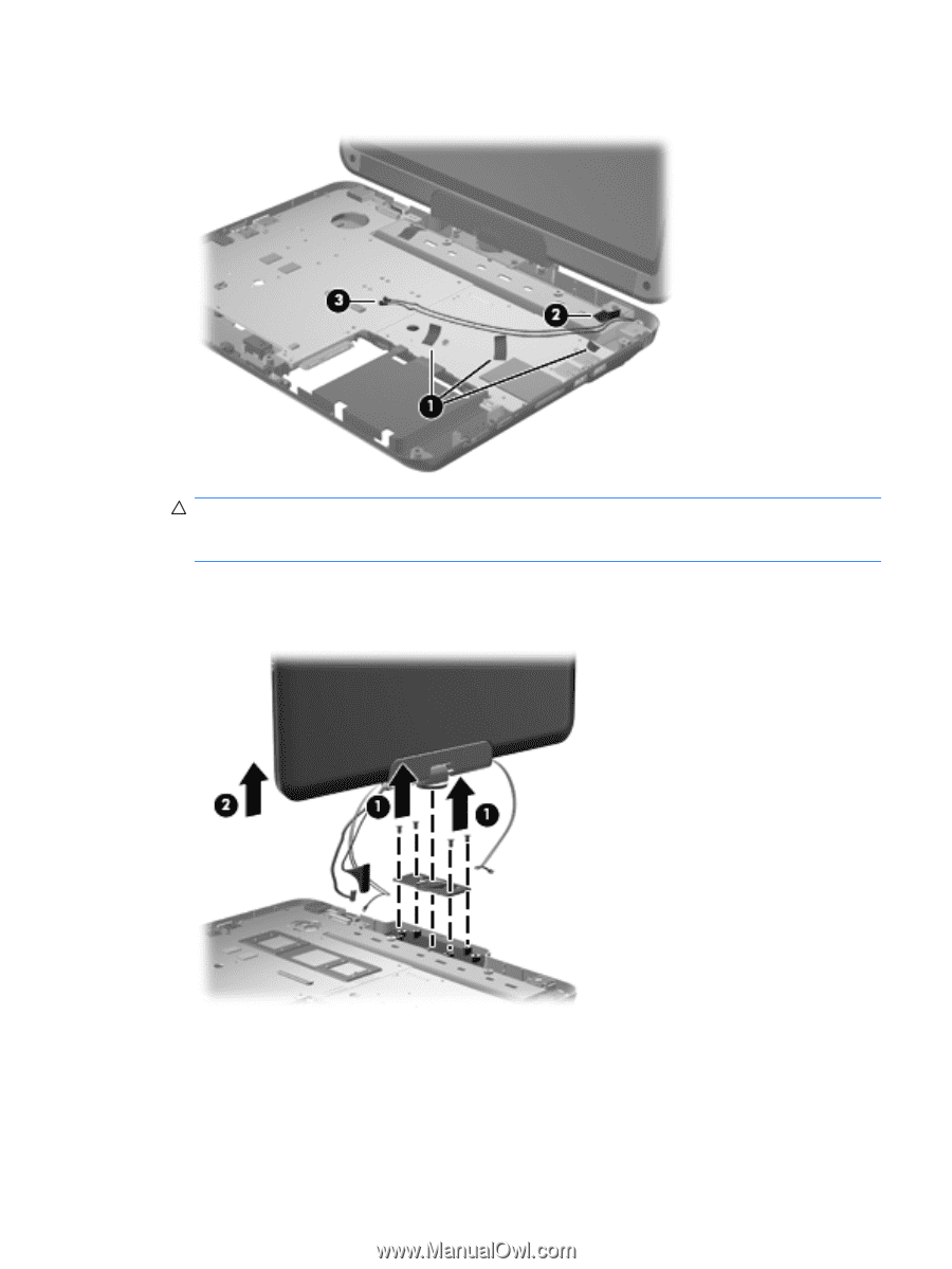
16. Release the wireless module antenna cables (3) from the opening in the system board. CAUTION: Support the display assembly when removing the following screws. Failure to support the display assembly can result in damage to the display assembly and other computer components. 17. Remove the four Phillips PM2.5×6.0 screws (1) that secure the display assembly to the computer. 18. Lift the display assembly (2) straight up and remove it. Reverse this procedure to install the display assembly. Component replacement procedures 59
-
 1
1 -
2
-
3
-
4
-
5
-
6
-
7
-
8
-
9
-
10
-
11
-
12
-
13
-
14
-
15
-
16
-
17
-
18
-
19
-
20
-
21
-
22
-
23
-
24
-
25
-
26
-
27
-
28
-
29
-
30
-
31
-
32
-
33
-
34
-
35
-
36
-
37
-
38
-
39
-
40
-
41
-
42
-
43
-
44
-
45
-
46
-
47
-
48
-
49
-
50
-
51
-
52
-
53
-
54
-
55
-
56
-
57
-
58
-
59
-
60
-
61
-
62
-
63
-
 64
64 -
 65
65 -
 66
66 -
 67
67 -
 68
68 -
 69
69 -
 70
70 -
 71
71 -
 72
72 -
 73
73 -
 74
74 -
75
-
76
-
77
-
78
-
79
-
80
-
81
-
82
-
83
-
84
-
85
-
86
-
87
-
88
-
89
-
90
-
91
-
92
-
93
-
94
-
95
-
96
-
97
-
98
-
99
-
100
-
101
-
102
-
103
-
104
-
105
-
106
-
107
-
108
-
109
-
110
-
111
-
112
-
113
 |
 |
16.
Release the wireless module antenna cables
(3)
from the opening in the system board.
CAUTION:
Support the display assembly when removing the following screws. Failure to
support the display assembly can result in damage to the display assembly and other computer
components.
17.
Remove the four Phillips PM2.5×6.0 screws
(1)
that secure the display assembly to the computer.
18.
Lift the display assembly
(2)
straight up and remove it.
Reverse this procedure to install the display assembly.
Component replacement procedures
59