HP Workstation xw6000 Optical Drive Installation for HP Workstations - Page 4
Installing the Drive
 |
View all HP Workstation xw6000 manuals
Add to My Manuals
Save this manual to your list of manuals |
Page 4 highlights
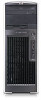
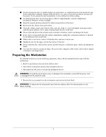
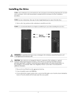
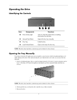
Installing the Drive NOTE: Your workstation may not be identical to the workstation in the following illustrations.If you need more information, refer to the documentation included with the workstation for drive installation procedures. NOTE: In some workstations, there may be drive length limitations for some of the drive bays. 1. Select a drive bay position on the workstation to install the new drive. NOTE: It is recommended that the next highest available bay be used when installing the new drive. Optical Drive Bays Å WARNING: To avoid the risk of serious injury or damage to the workstation, ensure that the power cord is unplugged from the electrical outlet. Ä CAUTION: Static electricity can damage the electronic components of the workstation or optional equipment. Before beginning these procedures, ensure that you are static-free by briefly touching a grounded metal object. In addition, avoid touching any exposed metal on the option board/chip or on the workstation's circuit boards. Refer to the "Regulatory Notices" section later in this document for additional information. 2. Remove the bezel blank from the appropriate drive bay. 3. If one is installed, remove the EMI filler. 4. If your optical drive requires guide screws, remove four M3 guide screws from the chassis behind the bezel (or from the diskette drive bracket under the access panel). 4
-
 1
1 -
 2
2 -
 3
3 -
 4
4 -
 5
5 -
 6
6 -
 7
7 -
 8
8 -
 9
9 -
 10
10 -
11
-
12
-
13
-
14
-
15
-
16
-
17
-
18
 |
 |