HP rp7440 User Service Guide, Fourth Edition - HP Integrity rx7640 and HP 9000 - Page 127
PCI-X OL* Card Divider LEDs, Cell Board LED Locations
 |
View all HP rp7440 manuals
Add to My Manuals
Save this manual to your list of manuals |
Page 127 highlights
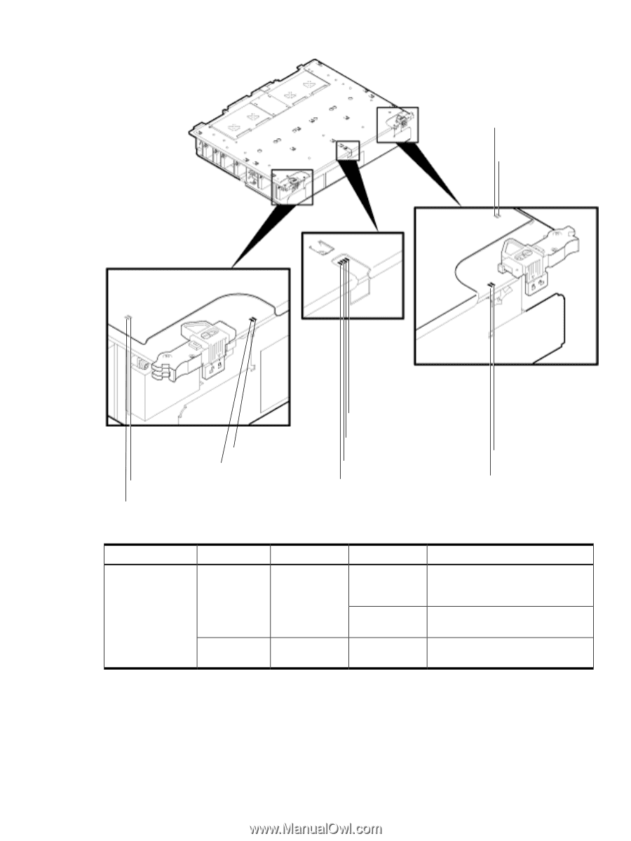
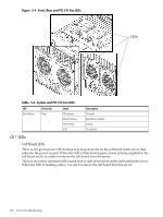
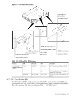
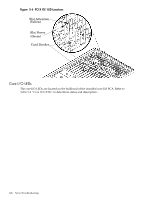
Figure 5-5 Cell Board LED Locations Voltage Margin Active (Red) Standby (Green) PDHC Heartbeat (Green) Cell Power (Green) Attention (Yellow) V3P3 Standby (Green) Manageability Fab (Green) SM (Green) BIB (Green) Cell Power (Green) Attention (Yellow) V12 Standby (Green) Table 5-5 Cell Board OL* LED Indicators Location LED On cell board Power (located in the server cabinet) Driven by Cell LPM Attention MP via GPM State On Green Off Flash Yellow Description 3.3 V Standby and Cell_Pwr_Good 3.3 V Standby off, or 3.3 V Standby on and no Cell_Pwr_Good Safe to remove the cell board from the system PCI-X OL* Card Divider LEDs The PCI-X OL* card LEDs are located on each of the 16 PCI-X slot dividers in the PCI-X card cage assembly area. The green power LED indicates whether power is supplied to the card slot. The yellow attention LED states are defined in Table 5-8 "OL* LED States". Server LED Indicators 127
-
 1
1 -
2
-
3
-
4
-
5
-
6
-
7
-
8
-
9
-
10
-
11
-
12
-
13
-
14
-
15
-
16
-
17
-
18
-
19
-
20
-
21
-
22
-
23
-
24
-
25
-
26
-
27
-
28
-
29
-
30
-
31
-
32
-
33
-
34
-
35
-
36
-
37
-
38
-
39
-
40
-
41
-
42
-
43
-
44
-
45
-
46
-
47
-
48
-
49
-
50
-
51
-
52
-
53
-
54
-
55
-
56
-
57
-
58
-
59
-
60
-
61
-
62
-
63
-
64
-
65
-
66
-
67
-
68
-
69
-
70
-
71
-
72
-
73
-
74
-
75
-
76
-
77
-
78
-
79
-
80
-
81
-
82
-
83
-
84
-
85
-
86
-
87
-
88
-
89
-
90
-
91
-
92
-
93
-
94
-
95
-
96
-
97
-
98
-
99
-
100
-
101
-
102
-
103
-
104
-
105
-
106
-
107
-
108
-
109
-
110
-
111
-
112
-
113
-
114
-
115
-
116
-
117
-
118
-
119
-
120
-
121
-
 122
122 -
 123
123 -
 124
124 -
 125
125 -
 126
126 -
 127
127 -
 128
128 -
 129
129 -
 130
130 -
 131
131 -
 132
132 -
133
-
134
-
135
-
136
-
137
-
138
-
139
-
140
-
141
-
142
-
143
-
144
-
145
-
146
-
147
-
148
-
149
-
150
-
151
-
152
-
153
-
154
-
155
-
156
-
157
-
158
-
159
-
160
-
161
-
162
-
163
-
164
-
165
-
166
-
167
-
168
-
169
-
170
-
171
-
172
-
173
-
174
-
175
-
176
-
177
-
178
-
179
-
180
-
181
-
182
-
183
-
184
-
185
-
186
-
187
-
188
-
189
-
190
-
191
-
192
-
193
-
194
-
195
 |
 |