HP rp7440 User Service Guide, Fourth Edition - HP Integrity rx7640 and HP 9000 - Page 26
Memory Subsystem, CPU Locations on Cell Board
 |
View all HP rp7440 manuals
Add to My Manuals
Save this manual to your list of manuals |
Page 26 highlights
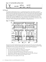
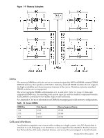
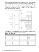
Figure 1-8 CPU Locations on Cell Board Socket 2 Socket 3 Cell Controller Socket 1 Socket 0 Memory Subsystem Figure 1-9 shows a simplified view of the memory subsystem. It consists of two independent access paths, each path having its own address bus, control bus, data bus, and DIMMs . Address and control signals are fanned out through register ports to the synchronous dynamic random access memory (SDRAM) on the DIMMs. The memory subsystem comprises four independent quadrants. Each quadrant has its own memory data bus connected from the cell controller to the two buffers for the memory quadrant. Each quadrant also has two memory control buses; one for each buffer. 26 HP Integrity rx7640 Server and HP 9000 rp7440 Server Overview
-
 1
1 -
2
-
3
-
4
-
5
-
6
-
7
-
8
-
9
-
10
-
11
-
12
-
13
-
14
-
15
-
16
-
17
-
18
-
19
-
20
-
 21
21 -
 22
22 -
 23
23 -
 24
24 -
 25
25 -
 26
26 -
 27
27 -
 28
28 -
 29
29 -
 30
30 -
 31
31 -
32
-
33
-
34
-
35
-
36
-
37
-
38
-
39
-
40
-
41
-
42
-
43
-
44
-
45
-
46
-
47
-
48
-
49
-
50
-
51
-
52
-
53
-
54
-
55
-
56
-
57
-
58
-
59
-
60
-
61
-
62
-
63
-
64
-
65
-
66
-
67
-
68
-
69
-
70
-
71
-
72
-
73
-
74
-
75
-
76
-
77
-
78
-
79
-
80
-
81
-
82
-
83
-
84
-
85
-
86
-
87
-
88
-
89
-
90
-
91
-
92
-
93
-
94
-
95
-
96
-
97
-
98
-
99
-
100
-
101
-
102
-
103
-
104
-
105
-
106
-
107
-
108
-
109
-
110
-
111
-
112
-
113
-
114
-
115
-
116
-
117
-
118
-
119
-
120
-
121
-
122
-
123
-
124
-
125
-
126
-
127
-
128
-
129
-
130
-
131
-
132
-
133
-
134
-
135
-
136
-
137
-
138
-
139
-
140
-
141
-
142
-
143
-
144
-
145
-
146
-
147
-
148
-
149
-
150
-
151
-
152
-
153
-
154
-
155
-
156
-
157
-
158
-
159
-
160
-
161
-
162
-
163
-
164
-
165
-
166
-
167
-
168
-
169
-
170
-
171
-
172
-
173
-
174
-
175
-
176
-
177
-
178
-
179
-
180
-
181
-
182
-
183
-
184
-
185
-
186
-
187
-
188
-
189
-
190
-
191
-
192
-
193
-
194
-
195
 |
 |
Figure 1-8 CPU Locations on Cell Board
Socket 2
Socket 3
Socket 1
Socket 0
Cell
Controller
Memory Subsystem
Figure 1-9
shows a simplified view of the memory subsystem. It consists of two independent
access paths, each path having its own address bus, control bus, data bus, and DIMMs . Address
and control signals are fanned out through register ports to the synchronous dynamic random
access memory (SDRAM) on the DIMMs.
The memory subsystem comprises four independent quadrants. Each quadrant has its own
memory data bus connected from the cell controller to the two buffers for the memory quadrant.
Each quadrant also has two memory control buses; one for each buffer.
26
HP Integrity rx7640 Server and HP 9000 rp7440 Server Overview