HP rp7440 User Service Guide, Fourth Edition - HP Integrity rx7640 and HP 9000 - Page 39
Environmental Temperature Sensor, Non-Operating Environment, Cooling, Internal Chassis Cooling
 |
View all HP rp7440 manuals
Add to My Manuals
Save this manual to your list of manuals |
Page 39 highlights
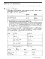
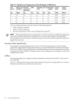
Environmental Temperature Sensor To ensure that the system is operating within the published limits, the ambient operating temperature is measured using a sensor placed near the chassis inlet, between the cell boards. Data from the sensor is used to control the fan speed and to initiate system overtemp shutdown. Non-Operating Environment The system is designed to withstand ambient temperatures between -40° to 70° C under non-operating conditions. Cooling Internal Chassis Cooling The cabinet incorporates front-to-back airflow across the cell boards and system backplane. Two 150 mm fans, mounted externally on the front chassis wall behind the cosmetic front bezel, push air into the cell section. Two 150 mm fans housed in cosmetic plastic fan carriers, mounted externally to the rear chassis wall, pull air through the cell section. Each fan is controlled by a smart fan control board, embedded in the fan module plastic housing. The smart fan control board receives fan control input from the system fan controller on the system backplane and returns fan status information to the system fan controller. The smart fan control board also controls the power and the pulse width modulated control signal to the fan and monitors the speed indicator back from the fan. The fan status LED is driven by the smart fan control board. Bulk Power Supply Cooling Cooling for the bulk power supplies (BPS) is provided by two 60 mm fans contained within each BPS. Air flows into the front of the BPS and is exhausted out of the top of the power supply through upward facing vents near the rear of the supply. The air is then ducted out of the rear of the chassis with minimal leakage into the cell airflow plenum. PCI/Mass Storage Section Cooling Six 92 mm fans located between the mass storage devices and the PCI card cage provide airflow through these devices. The PCI fans are powered with housekeeping power and run at full speed at all times. The air is pulled through the mass storage devices and pushed through the PCI Card Cage. Perforation is provided between the PCI bulkheads to allow adequate exhaust ventilation. Standby Cooling Several components within the chassis consume significant amounts of power while the system is in standby mode. The system fans run at a portion of full speed during standby to remove the resulting heat from the cabinet. The fans within the power supply will operate at full speed during standby. Typical Power Dissipation and Cooling Table 2-9 provides calculations for configurations for the HP 9000 rp7440 Server. For calculations for the HP Integrity rx7640 Server, see Chapter 7. Environmental Specifications 39
-
 1
1 -
2
-
3
-
4
-
5
-
6
-
7
-
8
-
9
-
10
-
11
-
12
-
13
-
14
-
15
-
16
-
17
-
18
-
19
-
20
-
21
-
22
-
23
-
24
-
25
-
26
-
27
-
28
-
29
-
30
-
31
-
32
-
33
-
 34
34 -
 35
35 -
 36
36 -
 37
37 -
 38
38 -
 39
39 -
 40
40 -
 41
41 -
 42
42 -
 43
43 -
 44
44 -
45
-
46
-
47
-
48
-
49
-
50
-
51
-
52
-
53
-
54
-
55
-
56
-
57
-
58
-
59
-
60
-
61
-
62
-
63
-
64
-
65
-
66
-
67
-
68
-
69
-
70
-
71
-
72
-
73
-
74
-
75
-
76
-
77
-
78
-
79
-
80
-
81
-
82
-
83
-
84
-
85
-
86
-
87
-
88
-
89
-
90
-
91
-
92
-
93
-
94
-
95
-
96
-
97
-
98
-
99
-
100
-
101
-
102
-
103
-
104
-
105
-
106
-
107
-
108
-
109
-
110
-
111
-
112
-
113
-
114
-
115
-
116
-
117
-
118
-
119
-
120
-
121
-
122
-
123
-
124
-
125
-
126
-
127
-
128
-
129
-
130
-
131
-
132
-
133
-
134
-
135
-
136
-
137
-
138
-
139
-
140
-
141
-
142
-
143
-
144
-
145
-
146
-
147
-
148
-
149
-
150
-
151
-
152
-
153
-
154
-
155
-
156
-
157
-
158
-
159
-
160
-
161
-
162
-
163
-
164
-
165
-
166
-
167
-
168
-
169
-
170
-
171
-
172
-
173
-
174
-
175
-
176
-
177
-
178
-
179
-
180
-
181
-
182
-
183
-
184
-
185
-
186
-
187
-
188
-
189
-
190
-
191
-
192
-
193
-
194
-
195
 |
 |