HP rp8440 Site Preparation Guide, Fourth Edition - HP Integrity rx8640, HP 900 - Page 26
Table 1-7 PCI-X Slot Boot Paths Cell 1
 |
View all HP rp8440 manuals
Add to My Manuals
Save this manual to your list of manuals |
Page 26 highlights
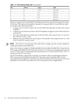
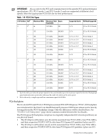
Table 1-7 PCI-X Slot Boot Paths Cell 1 (continued) Cell PCI Slot Ropes 1 4 14/15 1 5 6/7 1 6 4/5 1 7 2/3 1 8 1 Path 1/0/14/1/0 1/0/6/1/0 1/0/4/1/0 1/0/2/1/0 1/0/1/1/0 The server supports two internal SBAs. Each SBA provides the control and interfaces for eight PCI-X slots. The interface is through the rope bus (16 ropes per SBA). For each SBA, the ropes are divided in the following manner: • A single rope is routed to support the core I/O boards through LBAs located on the system backplane. • A single rope is routed to an LBA on the PCI backplane to support a slot for PCI and PCI-X cards (slot 8). • Six ropes are bundled into double ropes to three (3) LBAs. They support slots 1, 2, and 7 for PCI and PCI-X mode 1 cards. • Eight fat ropes are bundled into quad ropes to four (4) LBAs. They support slots 3, 4, 5, and 6 for PCI and PCI-X mode 2 cards. NOTE: PCI-X slots 1-7 are dual rope slots while slot 8 is a single rope slot. A rope is defined as a high-speed, point-to-point data bus. Each of the 16 slots is capable of 33 MHz/66 MHz PCI or 66 MHz/133 MHz PCI-X. Four slots in PCI-X support 266 MHz. All 16 PCI slots are keyed for 3.3 V connectors (accepting both Universal and 3.3 V cards). The PCI-X backplane does not provide any 5 V slots for the I/O cards. Table 1-8 summarizes the PCI-X slot types. The PCI-X backplane is physically one board, yet it behaves like two independent partitions. SBA 0 and its associated LBAs and eight PCI-X slots form one I/O partition. SBA 1 and its associated LBAs and eight PCI-X slots form the other I/O partition. One I/O partition can be reset separately from the other I/O partition but cannot be powered down independently. 26 HP Integrity rx8640 and HP 9000 rp8440 Server Overview
-
 1
1 -
2
-
3
-
4
-
5
-
6
-
7
-
8
-
9
-
10
-
11
-
12
-
13
-
14
-
15
-
16
-
17
-
18
-
19
-
20
-
 21
21 -
 22
22 -
 23
23 -
 24
24 -
 25
25 -
 26
26 -
 27
27 -
 28
28 -
 29
29 -
 30
30 -
 31
31 -
32
-
33
-
34
-
35
-
36
-
37
-
38
-
39
-
40
-
41
-
42
-
43
-
44
-
45
 |
 |
