HP rp8440 Site Preparation Guide, Fourth Edition - HP Integrity rx8640, HP 900 - Page 28
PCIe Slot Boot Paths, rates of 2.12Gb/s PCIe x8. - seu
 |
View all HP rp8440 manuals
Add to My Manuals
Save this manual to your list of manuals |
Page 28 highlights
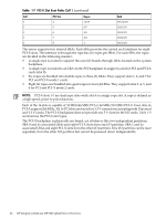
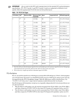
Each PCI/PCI-X slot has a host-to-PCI bridge associated with it, and each PCIe slot has a host-to-PCIe bridge associated with it. A dual slot hot swap controller chip and related logic is also associated with each pair of PCI or PCIe slots. The I/O chip on either cell location 0 or 1 is a primary I/O system interface. Upstream, the I/O chips communicate directly with the cell controller ASIC on the host cell board via a high bandwidth logical connection known as the HSS link.When installed in the SEU chassis within a fully configured system, the ASIC on cell location 0 connects to the cell controller chip on cell board 2, and the ASIC on cell location 1 connects to the cell controller chip on cell board 3 through external link cables. Downstream, the ASIC spawns 16 logical 'ropes' that communicate with the core I/O bridge on the system backplane, PCI interface chips, and PCIe interface chips. Each PCI chip produces a single 64-bit PCI-X bus supporting a single PCI or PCI-X add-in card. Each PCIe chip produces a single x8 PCI-Express bus supporting a single PCIe add-in card. The ropes in each I/O partition are distributed as follows: • One PCI-X ASIC is connected to each I/O chip with a single rope capable of peak data rates of 533Mb/s (PCIX-66). • Three PCI-X ASICs are connected to each I/O chip with dual ropes capable of peak data rates of 1.06Gb/s (PCIX-133). • Four PCIe ASICs are connected to each I/O chip with dual fat ropes capable of peak data rates of 2.12Gb/s (PCIe x8). In addition, each I/O chip provides an external single rope connection for the core I/O. Each PCI-Express slot on the PCIe I/O board is controlled by its own ASIC and is also independently supported by its own half of the dual hot swap controller. All PCIe slots are designed to be compliant with PCIe Rev.1.0. The PCI-Express I/O backplane will provide slot support for VAUX3.3, SMB*, and JTAG. PCIe Slot Boot Paths PCIe slot boot paths are directly leveraged from the PCI-X backplane. See Table 1-6 (page 25) and Table 1-7 (page 25) for more details. 28 HP Integrity rx8640 and HP 9000 rp8440 Server Overview
-
 1
1 -
2
-
3
-
4
-
5
-
6
-
7
-
8
-
9
-
10
-
11
-
12
-
13
-
14
-
15
-
16
-
17
-
18
-
19
-
20
-
21
-
22
-
 23
23 -
 24
24 -
 25
25 -
 26
26 -
 27
27 -
 28
28 -
 29
29 -
 30
30 -
 31
31 -
 32
32 -
 33
33 -
34
-
35
-
36
-
37
-
38
-
39
-
40
-
41
-
42
-
43
-
44
-
45
 |
 |
