HP rp8440 Site Preparation Guide, Fourth Edition - HP Integrity rx8640, HP 900 - Page 27
PCIe Backplane
 |
View all HP rp8440 manuals
Add to My Manuals
Save this manual to your list of manuals |
Page 27 highlights
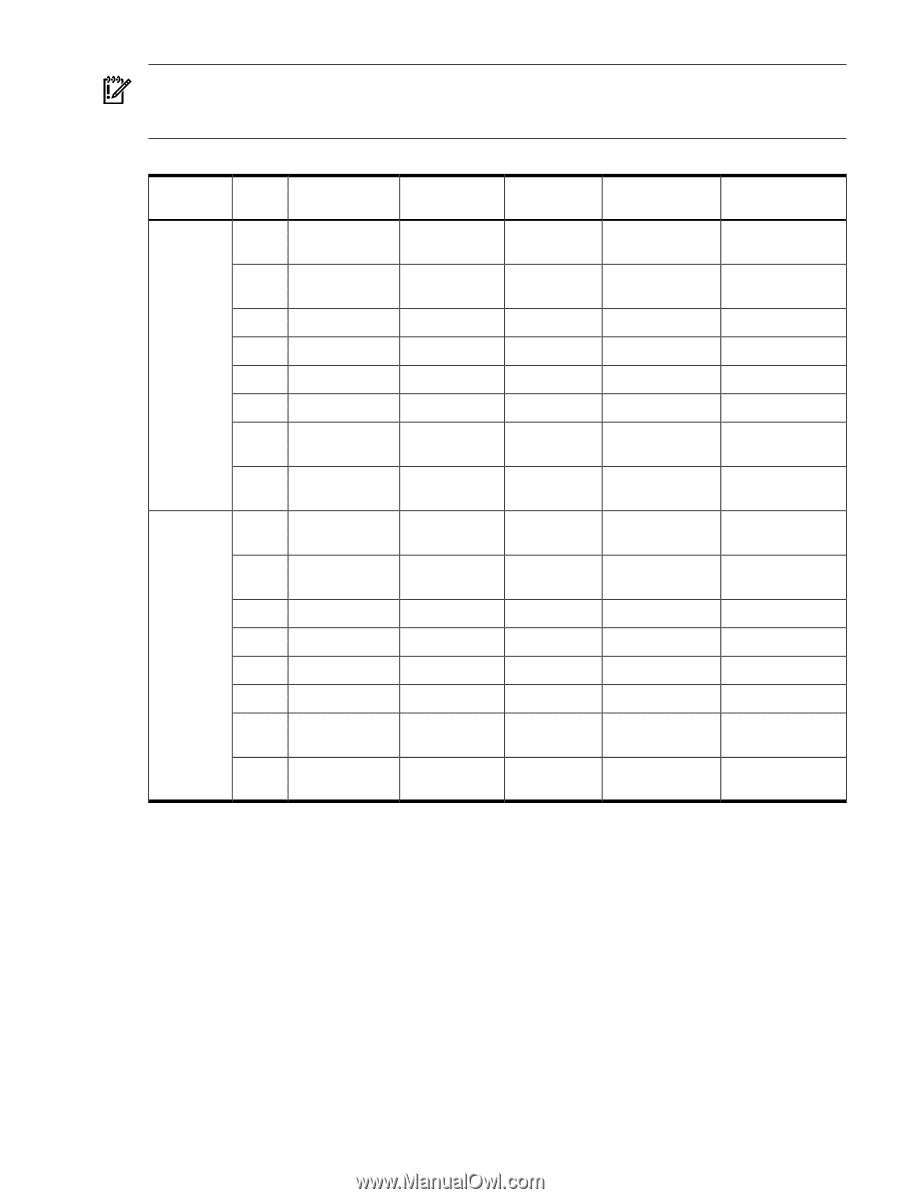
IMPORTANT: Always refer to the PCI card's manufacturer for the specific PCI card performance specifications. PCI, PCI-X mode 1, and PCI-X mode 2 cards are supported at different clock speeds. Select the appropriate PCI-X I/O slot for best performance. Table 1-8 PCI-X Slot Types I/O Partition Slot1 Maximum MHz 0 82 66 Maximum Peak Ropes Bandwidth 533 MB/s 001 Supported Cards PCI Mode Supported 3.3 V PCI or PCI-X Mode 1 7 133 1.06 GB/s 002/003 3.3 V PCI or PCI-X Mode 1 6 266 2.13 GB/s 004/005 3.3 V or 1.5 V PCI-X Mode 2 5 266 2.13 GB/s 006/007 3.3 V or 1.5 V PCI-X Mode 2 4 266 2.13 GB/s 014/015 3.3 V or 1.5 V PCI-X Mode 2 3 266 2.13 GB/s 012/013 3.3 V or 1.5 V PCI-X Mode 2 2 133 1.06 GB/s 010/011 3.3 V PCI or PCI-X Mode 1 1 133 82 66 1 1.06 GB/s 533 MB/s 008/009 001 3.3 V 3.3 V PCI or PCI-X Mode 1 PCI or PCI-X Mode 1 7 133 1.06 GB/s 002/003 3.3 V PCI or PCI-X Mode 1 6 266 2.13 GB/s 004/005 3.3 V or 1.5 V PCI-X Mode 2 5 266 2.13 GB/s 006/007 3.3 V or 1.5 V PCI-X Mode 2 4 266 2.13 GB/s 014/015 3.3 V or 1.5 V PCI-X Mode 2 3 266 2.13 GB/s 012/013 3.3 V or 1.5 V PCI-X Mode 2 2 133 1.06 GB/s 010/011 3.3 V PCI or PCI-X Mode 1 1 133 1.06 GB/s 008/009 3.3 V PCI or PCI-X Mode 1 1 Each slot will auto select the proper speed for the card installed up to the maximum speed for the slot. Placing high speed cards into slow speed slots will cause the card to be driven at the slow speed. 2 Slot is driven by a single rope and has a maximum speed of 66 MHz. PCIe Backplane The 16-slot (8 PCI and PCI-X; 8 PCI-Express) mixed PCI-X/PCI-Express ("PCIe") I/O backplane was introduced for the Dual-Core Intel® Itanium® processor 9100 Series release and is heavily leveraged from the PCI-X backplane design. Only the differences will be descibed here. See "PCI/PCI-X I/O Subsystem" (page 24) for common content between the two boards.. The PCI-Express I/O backplane comprises two logically independent I/O circuits (partitions) on one physical board. • The I/O chip in cell location zero (0) and its associated four PCI-X ASICs, four PCIe ASICs, and their respective PCI/PCI-X/PCIe slots form PCI-Express I/O partition 0 plus core I/O. • The I/O chip in cell location one (1) and its associated four PCI-X ASICs, four PCIe ASICs, and their respective PCI/PCI-X/PCIe slots form PCI-Express I/O partition 1 plus core I/O. Detailed Server Description 27
-
 1
1 -
2
-
3
-
4
-
5
-
6
-
7
-
8
-
9
-
10
-
11
-
12
-
13
-
14
-
15
-
16
-
17
-
18
-
19
-
20
-
21
-
 22
22 -
 23
23 -
 24
24 -
 25
25 -
 26
26 -
 27
27 -
 28
28 -
 29
29 -
 30
30 -
 31
31 -
 32
32 -
33
-
34
-
35
-
36
-
37
-
38
-
39
-
40
-
41
-
42
-
43
-
44
-
45
 |
 |