HP rp8440 Site Preparation Guide, Fourth Edition - HP Integrity rx8640, HP 900 - Page 42
A-2 Server Cabinet Template, A-2
 |
View all HP rp8440 manuals
Add to My Manuals
Save this manual to your list of manuals |
Page 42 highlights
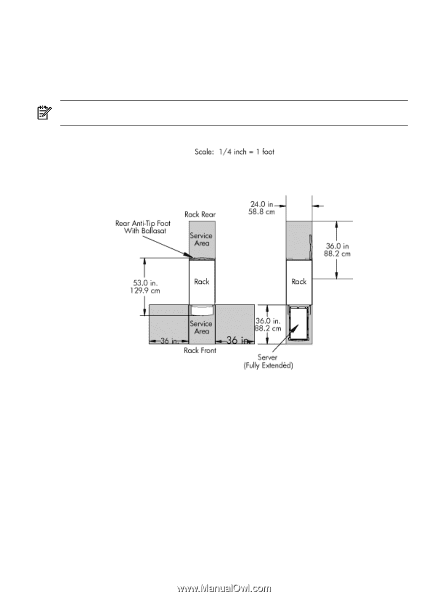
2. Cut and join them together (as necessary) to create a scale model floor plan of your computer room. 3. Remove a copy of each applicable equipment footprint template (Figure A-2). 4. Cut out each template selected in step 3; then place it on the floor plan grid created in step 2. 5. Position pieces until you obtain the desired layout, then fasten the pieces to the grid. Mark locations of computer room doors, air-conditioning floor vents, utility outlets, and so on. NOTE: Attach a reduced copy of the completed floor plan to the site survey. HP installation specialists use this floor plan during equipment installation. Figure A-2 Server Cabinet Template 42 Templates
-
 1
1 -
2
-
3
-
4
-
5
-
6
-
7
-
8
-
9
-
10
-
11
-
12
-
13
-
14
-
15
-
16
-
17
-
18
-
19
-
20
-
21
-
22
-
23
-
24
-
25
-
26
-
27
-
28
-
29
-
30
-
31
-
32
-
33
-
34
-
35
-
36
-
 37
37 -
 38
38 -
 39
39 -
 40
40 -
 41
41 -
 42
42 -
 43
43 -
 44
44 -
 45
45
 |
 |
2.
Cut and join them together (as necessary) to create a scale model floor plan of your computer
room.
3.
Remove a copy of each applicable equipment footprint template (
Figure A-2
).
4.
Cut out each template selected in step 3; then place it on the floor plan grid created in step
2.
5.
Position pieces until you obtain the desired layout, then fasten the pieces to the grid. Mark
locations of computer room doors, air-conditioning floor vents, utility outlets, and so on.
NOTE:
Attach a reduced copy of the completed floor plan to the site survey. HP installation
specialists use this floor plan during equipment installation.
Figure A-2 Server Cabinet Template
42
Templates