HP st5747 Troubleshooting Guide: HP t5740/t5745 Thin Clients and HP st5742/st5 - Page 24
WARNING, CAUTION, Remove the two screws securing the access plate to the chassis.
 |
View all HP st5747 manuals
Add to My Manuals
Save this manual to your list of manuals |
Page 24 highlights
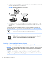
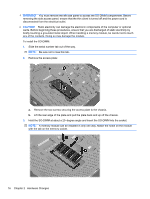
WARNING! You must remove the left side panel to access the SO-DIMM compartment. Before removing the side access panel, ensure that the thin client is turned off and the power cord is disconnected from the electrical outlet. CAUTION: Static electricity can damage the electronic components of the computer or optional cards. Before beginning these procedures, ensure that you are discharged of static electricity by briefly touching a grounded metal object. When handling a memory module, be careful not to touch any of the contacts. Doing so may damage the module. To install the SO-DIMM: 1. Slide the serial number tab out of the way. NOTE: Be sure not to lose this tab. 2. Remove the access plate: a. Remove the two screws securing the access plate to the chassis. b. Lift the rear edge of the plate and pull the plate back and up off the chassis. 3. Hold the SO-DIMM at about a 20-degree angle and insert the SO-DIMM into the socket. NOTE: A memory module can be installed in only one way. Match the notch on the module with the tab on the memory socket. 16 Chapter 2 Hardware Changes
-
 1
1 -
2
-
3
-
4
-
5
-
6
-
7
-
8
-
9
-
10
-
11
-
12
-
13
-
14
-
15
-
16
-
17
-
18
-
 19
19 -
 20
20 -
 21
21 -
 22
22 -
 23
23 -
 24
24 -
 25
25 -
 26
26 -
 27
27 -
 28
28 -
 29
29 -
30
-
31
-
32
-
33
-
34
-
35
-
36
-
37
-
38
-
39
-
40
-
41
-
42
-
43
-
44
-
45
-
46
-
47
-
48
-
49
-
50
-
51
-
52
-
53
 |
 |
