Hitachi C10FSB Instruction Manual - Page 16
Using an ink line, Position adjustment of laser line Only Model C10FSH - 10 sliding compound miter saw
 |
UPC - 717709007086
View all Hitachi C10FSB manuals
Add to My Manuals
Save this manual to your list of manuals |
Page 16 highlights
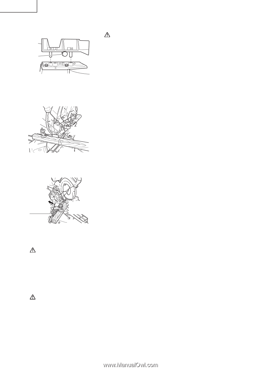
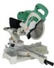
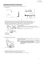
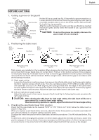
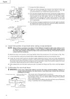
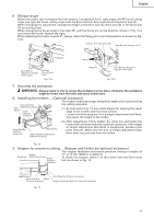
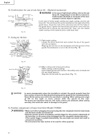
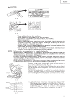
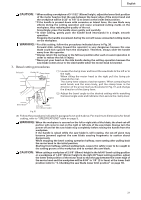
English 10. Confirmation for use of sub fence (A)...(Optional accessory) Sub Fence (A) WARNING: In the case of right bevel cutting, remove the sub fence (A). Supposing it is not able to remove it, It will contact the blade or some part of the tool, causing in serious injury to operator. 6mm Knob Bolt Fig. 15 In the case of direct angle cutting and angle cutting, use the sub fence (A). The sub fence (A) can be installed on the right side of the guide fence. Insert the rods of the sub fence (A) into the holes in the guide fence. Tighten the 6mm knob bolt which come with the sub fence (A) to secure the sub fence (A). Then, you can realize stable cutting of the material with a wide back face. 11. Using an ink line Saw Blade Groove Guard Workpiece 6mm Knob Bolt Marking (pre-marked) Fig. 16 (1) Right angle cutting Loosen the 6mm knob bolt and contact the tip of the guard with the workpiece. Aligning the ink line on the workpiece with the groove of the guard, the workpiece is cut on the ink line (Fig. 16). 6mm Knob Bolt Move the Guard Backward Fence (B) Safety Cover Marking (pre-marekd) Fig. 17 (2) Miter cutting and compound cutting (Miter cutting + bevel cutting) Upon lowering the motor section, the safety cover is raised and the saw blade appears. Align the ink line with the saw blade (Fig. 17). CAUTION: In some arrangements when the turntable is rotated, the guard projects from the fence surface. Loosen the 6mm knob bolt and push the guard to the retracted position. Never lift the safety cover while the saw blade is rotating. When cutting at an angle of 35° to the right or more, please slide the guard to the rear. The guard and sub-fence will not only make contact and adversely affect cutting accuracy, this could also result in damage to the guard. 12. Position adjustment of laser line (Only Model C10FSH) WARNING: * Make sure before plugging the power plug into the receptacle that the main body and the laser marker are turned off. * Exercise utmost caution in handling a switch trigger for the position adjustment of the laser line, as the power plug is plugged into the receptacle during operation. If the switch trigger is pulled inadvertently, the saw blade can rotate and result in unexpected accidents. * Do not remove the laser marker to be used for other purposes. 16
-
 1
1 -
2
-
3
-
4
-
5
-
6
-
7
-
8
-
9
-
10
-
 11
11 -
 12
12 -
 13
13 -
 14
14 -
 15
15 -
 16
16 -
 17
17 -
 18
18 -
 19
19 -
 20
20 -
 21
21 -
22
-
23
-
24
-
25
-
26
-
27
-
28
-
29
-
30
-
31
-
32
-
33
-
34
-
35
-
36
-
37
-
38
-
39
-
40
-
41
-
42
-
43
-
44
-
45
-
46
-
47
-
48
-
49
-
50
-
51
-
52
-
53
-
54
-
55
-
56
-
57
-
58
-
59
-
60
-
61
-
62
-
63
-
64
-
65
-
66
-
67
-
68
-
69
-
70
-
71
-
72
-
73
-
74
-
75
-
76
-
77
-
78
-
79
-
80
-
81
-
82
-
83
-
84
-
85
-
86
-
87
-
88
-
89
-
90
-
91
-
92
-
93
-
94
-
95
-
96
 |
 |