Hitachi DK23BA-20 Owners Manual - Page 21
Attention for HDD Installation, 3 Device Address Setting DRIVE 0/DRIVE 1
 |
View all Hitachi DK23BA-20 manuals
Add to My Manuals
Save this manual to your list of manuals |
Page 21 highlights
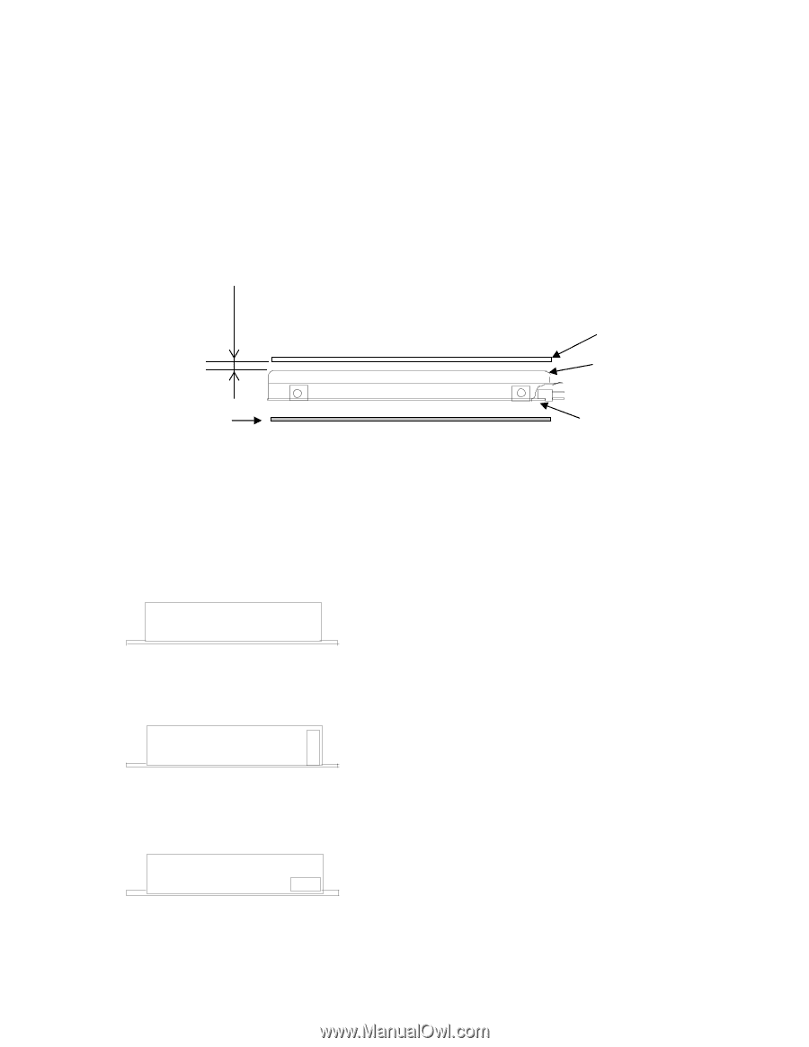
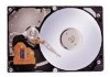
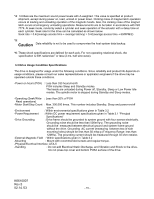
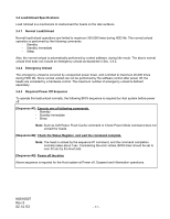
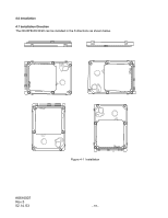
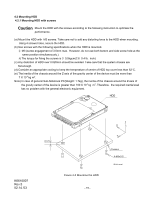
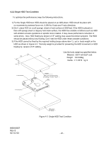
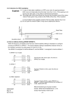
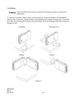
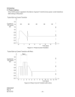
4.2.3 Attention for HDD Installation Caution (1) In case of steel plate installation on HDD cover side, the spacing between HDD cover and steel plate should be kept more than 2 mm. If this spacing is not sheet kept for the steel plate, it may affect Load/Unload mechanism. (2) The PCBA side of the drive should be covered with insulation sheet if the active metal of host system may contact to the PCBA of the drive. If the insulation is not provided for the possible contact of the live metal, failures may occur. (3) Do not push the bottom PCBA. It may cause catastrophic failures. More than 2 mm Steel Plate HDD Cover Insulation sheet PCBA 4.3 Device Address Setting (DRIVE 0/DRIVE 1) When the device is connected to the host bus, Device address setting is necessary to configure a device as DRIVE 0 or DRIVE 1. The device address setting is established between drives on the interface connector by using jumper 0-2 (pin # A, B, D) The DRIVE 0 is assigned to device address 0, and the DRIVE 1 is assigned to device address 1. 1) DRIVE 0 (or single) 43 5 31 O O O O O O O O 44 642 CA O O O O DB If all of pins A,B, D are open, the drive is DRIVE 0(or single). 2) DRIVE 1 43 5 31 O O O O O O O O 44 642 CA O O O O DB If jumper Position A-B is used, the drive is DRIVE 1. 3) CSEL Selection 43 5 31 O O O O O O O O 44 642 CA O O O O DB K6610007 Rev.5 02.14.'03 If jumper Position B-D is used, DRIVE 0 or DRIVE 1 setting is determined by the condition of CSEL signal (pin# 28). (Recommended type of jumper socket) Vender: IRISO ELECTRONICS CO., LTD. Vender Part Number: 9721HJ-GF - 21 -
-
 1
1 -
2
-
3
-
4
-
5
-
6
-
7
-
8
-
9
-
10
-
11
-
12
-
13
-
14
-
15
-
 16
16 -
 17
17 -
 18
18 -
 19
19 -
 20
20 -
 21
21 -
 22
22 -
 23
23 -
 24
24 -
 25
25 -
 26
26 -
27
-
28
-
29
-
30
-
31
-
32
-
33
-
34
-
35
-
36
-
37
-
38
-
39
-
40
-
41
-
42
-
43
-
44
-
45
-
46
-
47
-
48
-
49
-
50
-
51
-
52
-
53
-
54
-
55
-
56
-
57
-
58
-
59
-
60
-
61
-
62
-
63
-
64
-
65
-
66
-
67
-
68
-
69
-
70
-
71
-
72
-
73
-
74
-
75
-
76
-
77
-
78
-
79
-
80
-
81
-
82
-
83
-
84
-
85
-
86
-
87
-
88
-
89
-
90
-
91
-
92
-
93
-
94
-
95
-
96
-
97
-
98
-
99
-
100
-
101
-
102
-
103
-
104
-
105
-
106
-
107
-
108
-
109
-
110
-
111
-
112
-
113
-
114
 |
 |