Hitachi DK23BA-20 Owners Manual - Page 67
Command data structure, Error data structure
 |
View all Hitachi DK23BA-20 manuals
Add to My Manuals
Save this manual to your list of manuals |
Page 67 highlights
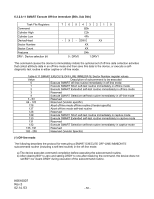
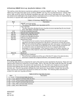
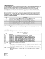
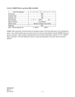
Command data structure The fifth command data structure contains the command or reset for which the error is being reported. The fourth command data structure contains the command or reset that preceded the command or reset for which the error is being reported, the third command data structure contains the command or reset preceding the one in the fourth command data structure, etc. If fewer than four commands and resets preceded the command or reset for which the error is being reported, the unused command data structures are zero filled. If the command data structure represents a command or software reset, the content of the command data structure is as shown in following table. If the command data structure represents a hardware reset, the content of byte n is FFh, the content of bytes n+1 through n+7 are not valid, and the content of bytes n+8 through n+11 contains the timestamp. Byte n n+1 n+2 n+3 n+4 n+5 n+6 n+7 n+8 ~ n+11 Description Content of Device Control register when the Command register was written. Content of Features register when the Command register was written. Content of Sector Count register when the Command register was written. Content of Sector Number register when the Command register was written. Content of Cylinder Low register when the Command register was written. Content of Cylinder High register when the Command register was written. Content of Device/Head register when the Command register was written. Content written to the Command register. Timestamp This is the time since power-on in milliseconds when command acceptance occurred. Error data structure The error data structure contains the error description of the command for which an error was reported as described in following. Byte n n+1 n+2 n+3 n+4 n+5 n+6 n+7 n+8 ~ n+25 n+27 n+28 ~ n+29 Table 6.15 Error data structure Description Reserved Content of the Error register after command completion occurred. Content of the Sector Count register after command completion occurred. Content of the Sector Number register after command completion occurred. Content of the Cylinder Low register after command completion occurred. Content of the Cylinder High register after command completion occurred. Content of the Device/Head register after command completion occurred. Content written to the Status register after command completion occurred. Extended error information (Vendor Specific) State This contains a value indicating the state of the device when command was written to the Command register or the reset occurred as described below. 01h: Sleep 02h: Standby 03h: Active/Idle with BSY cleared to zero 04h: Executing SMART off-line or self-test Life timestamp This contains the power-on lifetime of the device in hours when command completion occurred. K6610007 Rev.5 02.14.'03 - 67 -
-
 1
1 -
2
-
3
-
4
-
5
-
6
-
7
-
8
-
9
-
10
-
11
-
12
-
13
-
14
-
15
-
16
-
17
-
18
-
19
-
20
-
21
-
22
-
23
-
24
-
25
-
26
-
27
-
28
-
29
-
30
-
31
-
32
-
33
-
34
-
35
-
36
-
37
-
38
-
39
-
40
-
41
-
42
-
43
-
44
-
45
-
46
-
47
-
48
-
49
-
50
-
51
-
52
-
53
-
54
-
55
-
56
-
57
-
58
-
59
-
60
-
61
-
 62
62 -
 63
63 -
 64
64 -
 65
65 -
 66
66 -
 67
67 -
 68
68 -
 69
69 -
 70
70 -
 71
71 -
 72
72 -
73
-
74
-
75
-
76
-
77
-
78
-
79
-
80
-
81
-
82
-
83
-
84
-
85
-
86
-
87
-
88
-
89
-
90
-
91
-
92
-
93
-
94
-
95
-
96
-
97
-
98
-
99
-
100
-
101
-
102
-
103
-
104
-
105
-
106
-
107
-
108
-
109
-
110
-
111
-
112
-
113
-
114
 |
 |
