Hitachi DK23FB-60 Owners Manual - Page 66
Summary SMART Error Log, Log Sector Address = 01h]
 |
UPC - 706569123807
View all Hitachi DK23FB-60 manuals
Add to My Manuals
Save this manual to your list of manuals |
Page 66 highlights
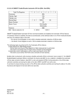
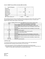
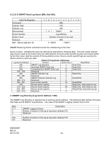
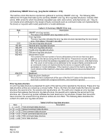
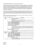
(2) Summary SMART Error Log [Log Sector Address = 01h] The last five errors that device reported are gathered in summary SMART error log. The following table defines the 512 bytes that make up the summary SMART error log. Error log data structures includes UNC errors, IDNF errors for which the address requested was valid, servo errors, write fault errors, etc. They do not include errors attributed to the receipt of faulty commands such as command codes not implemented by the device or requests with invalid parameters or invalid addresses. Byte 0 1 2-91 92-181 182-271 272-361 362-451 452-453 454-510 511 Table 6.13 Summary SMART Error Log Description SMART error log version The value of the SMART error log version is 01h. Error log index The error log index indicates the error log data structure representing the most recent error. Only values 1 through 5 are valid. First error log data structure Second error log data structure Third error log data structure Fourth error log data structure Fifth error log data structure Device error count This contains the total number of errors attributable to the device that have been reported by the device during the life of the device. These errors include UNC errors, IDNF errors for which the address requested was valid, servo errors, write fault errors, etc. This count is not include errors attributed to the receipt of faulty commands such as commands codes not implemented by the device or requests with invalid parameters or invalid addresses. If the maximum value for this field is reached, the count remains at the maximum value when additional errors are encountered and logged. Reserved Data structure checksum This is the two's complement of the sum of the first 511 bytes in the data structure. Each byte is added with unsigned arithmetic, and overflow is ignored. Error log data structure An error log data structure is presented for each of the last five errors reported by the device. These error log data structure entries are viewed as a circular buffer. That is, the first error shall create the first error log data structure; the second error, the second error log structure; etc. The sixth error creates an error log data structure that replaces the first error log data structure; the seventh error replaces the second error log structure, etc. The error log pointer indicates the most recent error log structure. If fewer than five errors have occurred, the unused error log structure entries are zero filled. The following table describes the content of a valid error log data structure. Byte n ~ n+11 n+12 ~ n+23 n+24 ~ n+35 n+36 ~ n+47 n+48 ~ n+59 n+60 ~ n+89 Table 6.14 Error log data structure Description First command data structure Second command data structure Third command data structure Fourth command data structure Fifth command data structure Error data structure K6610007 Rev.5 02.14.'03 - 66 -
-
 1
1 -
2
-
3
-
4
-
5
-
6
-
7
-
8
-
9
-
10
-
11
-
12
-
13
-
14
-
15
-
16
-
17
-
18
-
19
-
20
-
21
-
22
-
23
-
24
-
25
-
26
-
27
-
28
-
29
-
30
-
31
-
32
-
33
-
34
-
35
-
36
-
37
-
38
-
39
-
40
-
41
-
42
-
43
-
44
-
45
-
46
-
47
-
48
-
49
-
50
-
51
-
52
-
53
-
54
-
55
-
56
-
57
-
58
-
59
-
60
-
 61
61 -
 62
62 -
 63
63 -
 64
64 -
 65
65 -
 66
66 -
 67
67 -
 68
68 -
 69
69 -
 70
70 -
 71
71 -
72
-
73
-
74
-
75
-
76
-
77
-
78
-
79
-
80
-
81
-
82
-
83
-
84
-
85
-
86
-
87
-
88
-
89
-
90
-
91
-
92
-
93
-
94
-
95
-
96
-
97
-
98
-
99
-
100
-
101
-
102
-
103
-
104
-
105
-
106
-
107
-
108
-
109
-
110
-
111
-
112
-
113
-
114
 |
 |
