Honeywell CT3451 Owner's Manual - Page 2
Caution - thermostat
 |
View all Honeywell CT3451 manuals
Add to My Manuals
Save this manual to your list of manuals |
Page 2 highlights
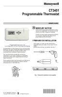
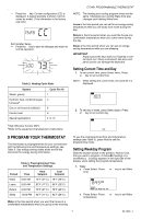
CT3451 PROGRAMMABLE THERMOSTAT 2 REMOVE OLD THERMOSTAT ❑ Test to be sure your heating and air conditioning systems (where applicable) are working correctly. If not, contact your local heating/air conditioning dealer. To avoid compressor damage, do not operate the cooling system when outdoor temperature is below 50°F (10°C). Table 1. Compatibility Chart. Gas-standing pilot Gas-electronic ignition Gas-fired boilers System Type Gas-750 millivolt Oil-fired boilers Oil-fired furnace Electric furnace Electric air conditioning Single stage heat pumps (no backup or auxiliary heat) Baseboard electric (120/240 line volt) Multistage heat pumps/multistage equipment Compatible With CT3451 Yes Yes Yesa Yes Yesa Yes Yes Yes Yes No No Not compatible with any 120/240 volt circuit. aCompatible with 2-wire Honeywell zone valves. Isolating relay required for zone valves that have a 3-wire thermostat connection. CAUTION Equipment Damage Hazard. Handling wires during installation can damage equipment. Disconnect power at furnace or main breaker/ fuse box before beginning installation. ❑ Carefully unpack your new thermostat and wallplate and save package of screws, instructions and receipt. ❑ Remove the cover from the old thermostat. If it does not snap off when pulled firmly from the bottom, check for screw that locks on the cover. ❑ Loosen screws holding thermostat to subbase, wallplate or wall and lift away. ❑ Disconnect wires from old thermostat or subbase. As you disconnect each wire, use the wiring labels (enclosed) to label each wire with the old terminal designation. If there are only two wires, they do not require labeling. Wrap wires around a pencil to keep them from falling back into the wall as shown in Fig. 2. WIRES THROUGH WALL OPENING Replacing Clock WIth C or C1 Clock Terminals If you are replacing a Honeywell Chronotherm® Thermostat, you may find one or two wires that go to the C or C1 clock terminals on the Chronotherm® Thermostat wiring wallplate. Do not allow them to touch, or you can damage your transformer. Disconnect the wires and wrap them separately using electrical tape; do not wrap them together. Do not place the wires where they can interfere with the new thermostat operation. Record the colors and terminal designation labels of the remaining wires. Six or More Thermostat Wires If there are six or more wires connected to the thermostat (excluding clock wires attached to terminals), you probably have a variation of a multistage heat pump or other multistage system. The thermostat is not compatible with these systems, so return the product to your retailer. If you want information about which programmable thermostats work with your system, visit our Web site at www.honeywell.com/yourhome or call the customer information line at 1-800-468-1502. M5136 Fig. 2. Wrapping wires around pencil. Three Thermostat Wires If you have three wires for heating only and can operate the fan using the Fan On switch, this thermostat works with your system. However, some hot water (zoned) heating systems have three thermostat wires. The thermostat works only if a contractor installs an isolating relay on these systems. For details, contact a local heating/cooling contractor. 69-1620-1 2
-
 1
1 -
 2
2 -
 3
3 -
 4
4 -
 5
5 -
 6
6 -
 7
7 -
 8
8 -
9
-
10
-
11
-
12
 |
 |