Honeywell CT3451 Owner's Manual - Page 5
Adjust Fan Operation, Switch, Mount Thermostat To, Wallplate, Installing And Replacing, Batteries - thermostats
 |
View all Honeywell CT3451 manuals
Add to My Manuals
Save this manual to your list of manuals |
Page 5 highlights
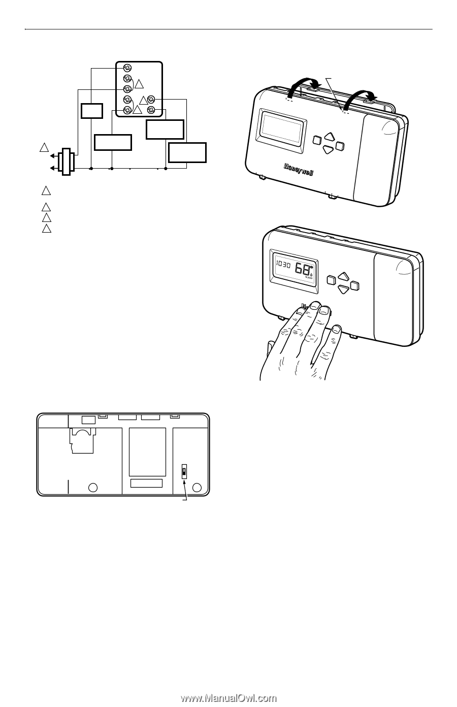
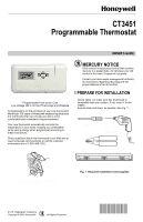
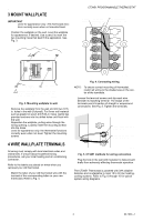
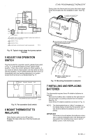
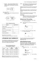
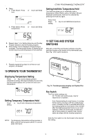
T8002 THERMOSTAT G Rc FAN RELAY R 3 W 4B Y 2 O 1 L1 (HOT) L2 COMPRESSOR CONTACTOR COOL CHANGEOVER VALVE HEAT CHANGEOVER VALVE TRANSFORMER 1 POWER SUPPLY. PROVIDE DISCONNECT MEANS AND OVERLOAD PROTECTION AS REQUIRED. 2 JUMPER Y TO W. 3 JUMPER R TO Rc. 4 USE EITHER O OR B FOR HEAT PUMP CHANGEOVER. M20512 CT3451 PROGRAMMABLE THERMOSTAT ❑ Swing down the thermostat and press the lower edge of the thermostat onto the wallplate to latch. See Fig. 12. DASHED LINES INDICATE TABS ON BACK OF THERMOSTAT Hold Select AuFtoANOn Cool SOYfSf THEeMat A ENGAGE TABS AT TOP OF THERMOSTAT WITH SLOTS ON WALLPLATE. Fig. 10. Typical single-stage heat pump system hookup. 5 ADJUST FAN OPERATION SWITCH The thermostat fan operation switch, labeled fuel switch in Fig. 11, is set at the factory in the F (gas/oil fuel) position. This is the correct setting for most systems. If you have an electric heat system, set the switch to the E (electric) position. The E setting allows the fan to turn on immediately with the heating equipment in a system where the G terminal is connected.See Fig. 11. PM TUE AuFtoANOn Hold Select CoolSOYfSf THEeMat B PRESS LOWER EDGE OF CASE TO LATCH. M20513 Fig. 12. Mounting thermostat to wallplate. E F FAN OPERATION (FUEL) SWITCH M20530 Fig. 11. Fan operation (fuel) switch. 6 MOUNT THERMOSTAT TO WALLPLATE ❑ Slide System switch to the Off position. ❑ Engage the tabs at the top of the thermostat and wallplate. 7 INSTALLING AND REPLACING BATTERIES The thermostat requires three AA alkaline batteries to operate: ❑ Remove the battery door, located on the right side of the thermostat, by pulling outward from the bottom. See Fig. 13. ❑ Insert three AA alkaline batteries as shown in Fig. 13. NOTE: The thermostat shows a "bAtLo" message on the digital display to alert the homeowner one to two months before the batteries run out completely. IMPORTANT Homeowner should replace the batteries once a year to prevent leakage and/or the heating/cooling system from shutting down due to lack of battery power in the thermostat. 5 69-1620-1
-
 1
1 -
 2
2 -
 3
3 -
 4
4 -
 5
5 -
 6
6 -
 7
7 -
 8
8 -
 9
9 -
 10
10 -
 11
11 -
12
 |
 |