Honeywell CT8775A Owner's Manual - Page 10
Step 8. customize the thermostat, Set Fuel Switch (CT8775C Only), DIP Switch, Set Heat Cycle Rate
 |
UPC - 085267244138
View all Honeywell CT8775A manuals
Add to My Manuals
Save this manual to your list of manuals |
Page 10 highlights
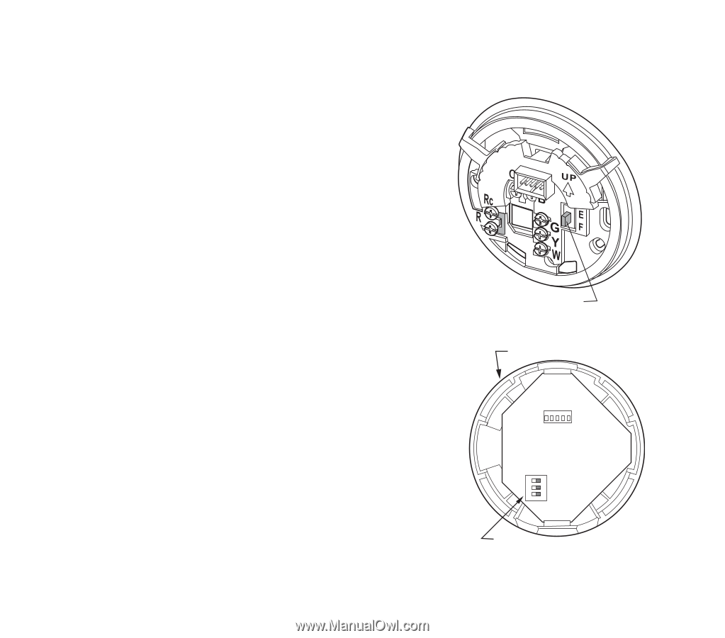
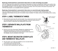
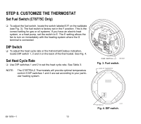
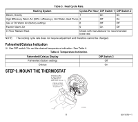
STEP 8. CUSTOMIZE THE THERMOSTAT Set Fuel Switch (CT8775C Only) ❑ To adjust the fuel switch, locate the switch labeled E/F on the wallplate (see Fig. 3). The fuel switch is factory set in the F position. This is the correct setting for gas or oil systems. If you have an electric heat system, or a heat pump, set the switch to E. The E setting allows the fan to turn on immediately with the heating system where the G terminal is connected. DIP Switch ❑ To adjust the heat cycle rate or the Fahrenheit/Celsius indication, locate DIP switch 1, 2 and 3 on the back of the thermostat. See Fig. 4. Set Heat Cycle Rate ❑ Use DIP switches 1 and 2 to set the heat cycle rate. See Table 3. NOTE: The CT8775A,C Thermostats will provide optimal temperature control if DIP switches 1 and 2 are set according to your particular heating system. FUEL SWITCH M19497 Fig. 3. Fuel switch. BACK OF THERMOSTAT ON 123 69-1676-1 DIP SWITCH M19567 Fig. 4. DIP switch. 10
-
 1
1 -
2
-
3
-
4
-
 5
5 -
 6
6 -
 7
7 -
 8
8 -
 9
9 -
 10
10 -
 11
11 -
 12
12 -
 13
13 -
 14
14 -
 15
15 -
16
-
17
-
18
-
19
-
20
 |
 |