Honeywell CT8775A Owner's Manual - Page 7
Mount Decorator Cover Plate Required and Wallplate onto Electrical Box
 |
UPC - 085267244138
View all Honeywell CT8775A manuals
Add to My Manuals
Save this manual to your list of manuals |
Page 7 highlights
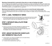
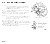
. Mount Decorator Cover Plate (Required) and Wallplate onto Electrical Box ❑ Pull the wires through the wiring hole on the decorator cover plate. ❑ Place the decorator cover plate against the electrical box so that the UP indicator in the middle of the decorator cover plate is pointing up. ❑ Line up the screw slots on the decorator cover plate with the electrical box screw holes, and attach the decorator cover plate to the electrical box with two 1/2 in. screws. ❑ Pull the wires through the wiring hole on the wallplate. ❑ Place the wallplate over the decorator cover plate. Turn the wallplate until the wiring holes are aligned and the two screw holes on the left and right side of the wallplate line up with the screw holes on the decorator cover plate. ❑ Attach the wallplate to the decorator cover plate with the two 3/8 in. screws. BOÎTE ÉLECTRIQUE PLAQUE D'ADAPTATION DÉCORATIVE VIS 1/2 PO (2) PLAQUE DE COMMUTATION VIS 3/8 PO (2) A1 TROUS DE CÂBLAGE 1 SI LA BOÎTE ÉLECTRIQUE EST HORIZONTALE, MONTER LA PLAQUE D'ADAPTATION DÉCORATIVE DANS LA POSITION ILLUSTRÉE, MAIS INSÉRER LES VIS DANS LE TROU DE MONTAGE «A». MF19494 Fig. 2. Mount decorator cover plate (required) and wallplate onto electrical box (heating-cooling wallplate shown). 7 69-1676-1
-
 1
1 -
 2
2 -
 3
3 -
 4
4 -
 5
5 -
 6
6 -
 7
7 -
 8
8 -
 9
9 -
 10
10 -
 11
11 -
 12
12 -
13
-
14
-
15
-
16
-
17
-
18
-
19
-
20
 |
 |
