Honeywell HE360A Owners Manual - Page 14
Fig. 9. Attaching sail to switch., Fig. 10. Inserting sail switch in direction of airflow.
 |
View all Honeywell HE360A manuals
Add to My Manuals
Save this manual to your list of manuals |
Page 14 highlights
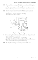
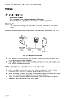
HE360A,B POWERED FLOW-THROUGH HUMIDIFIER - LOOSEN SETSCREW - INSERT SAIL CORD - TUCK CORD INTO TAB SLOTS - TIGHTEN SETSCREW SAIL M31017 Fig. 9. Attaching sail to switch. 5. Press together the sides of the wire loop. Insert the sail into the duct. (When in the Off position, the sail should point into the direction of airflow as shown in Fig.10.) AIRFLOW M20178 Fig. 10. Inserting sail switch in direction of airflow. 69-1176-04 14
-
 1
1 -
2
-
3
-
4
-
5
-
6
-
7
-
8
-
 9
9 -
 10
10 -
 11
11 -
 12
12 -
 13
13 -
 14
14 -
 15
15 -
 16
16 -
 17
17 -
 18
18 -
 19
19 -
20
-
21
-
22
-
23
-
24
 |
 |

HE360A,B POWERED FLOW-THROUGH HUMIDIFIER
69-1176—04
14
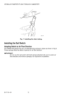
Fig. 9. Attaching sail to switch.
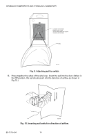
5.
Press together the sides of the wire loop. Insert the sail into the duct. (When in
the Off position, the sail should point into the direction of airflow as shown in
Fig.10.)
Fig. 10. Inserting sail switch in direction of airflow.
– LOOSEN SETSCREW
– INSERT SAIL CORD
– TUCK CORD INTO TAB SLOTS
– TIGHTEN SETSCREW
SAIL
M31017
M20178
AIRFLOW