Honeywell HE360A Owners Manual - Page 6
Warning, Caution - flow through
 |
View all Honeywell HE360A manuals
Add to My Manuals
Save this manual to your list of manuals |
Page 6 highlights
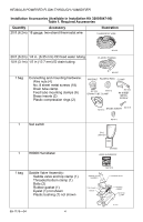
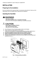
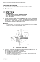
HE360A,B POWERED FLOW-THROUGH HUMIDIFIER INSTALLATION Preparing for the Installation Be sure to identify all the required (Table 1) accessories (included) and make sure the appropriate tools are available before beginning the installation. Installing the Humidifier WARNING Hazardous Voltage Can cause personal injury or equipment damage. Do not cut or drill into any air conditioning or electrical accessory. CAUTION Sharp Edges Installation Hazard. Can cause personal injury. Wear gloves and safety glasses. 1. Turn off power to the air handing system at the circuit breaker. 2. Draw a level line on the plenum in the location chosen for the humidifier. (Leveling assures optimal humidifier performance.) 3. Locate the template (form number 69-1651 included in the box). 4. Tape the template in position and trace around the template. 5. Remove the template and carefully cut the rectangular opening. 6. Disassemble the humidifier; remove the cover and take out the humidifier pad assembly. See Fig. 1. FEED TUBE NOZZLE WATER DISTRIBUTION TRAY HUMIDIFIER PAD ASSEMBLY 69-1176-04 THUMB SCREW COVER ASSEMBLY HUMIDIFIER HOUSING M12809 Fig. 1. Disassembling humidifier. 6
-
 1
1 -
 2
2 -
 3
3 -
 4
4 -
 5
5 -
 6
6 -
 7
7 -
 8
8 -
 9
9 -
 10
10 -
 11
11 -
 12
12 -
13
-
14
-
15
-
16
-
17
-
18
-
19
-
20
-
21
-
22
-
23
-
24
 |
 |
