Honeywell HE360A Owners Manual - Page 16
Wiring - install
 |
View all Honeywell HE360A manuals
Add to My Manuals
Save this manual to your list of manuals |
Page 16 highlights
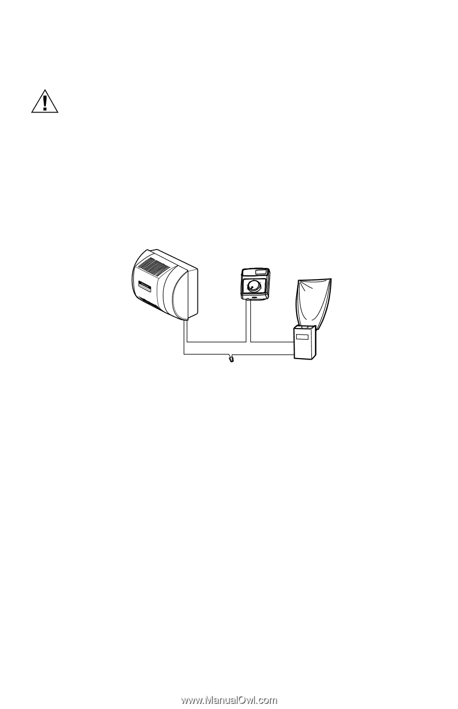
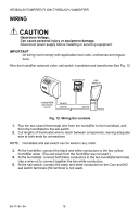
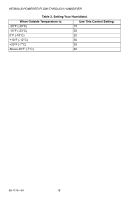
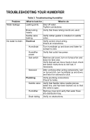
HE360A,B POWERED FLOW-THROUGH HUMIDIFIER WIRING CAUTION Hazardous Voltage. Can cause personal injury or equipment damage. Disconnect power supply before installing or servicing equipment. IMPORTANT All wiring must comply with applicable local code, ordinances and regulations. Wire the humidifier solenoid valve, sail switch, humidistat and transformer.See Fig. 12. HUMIDISTAT Humidity Control Régulateur d'humidité OUTDOOR TEMPERATURE -20 ¡F -30 ¡C -10 ¡F -25 ¡C 0 ¡F -20 ¡C +10 ¡F -10 ¡C +20 ¡F -5 ¡C Over 20 ¡F Over 0 ¡C HUMIDITY SETTING 15% 20% 25% 30% 35% 40% SAIL SWITCH HUMIDIFIER SOLENOID VALVE BLACK WHITE WHITE M20205 Fig. 12. Wiring the controls. 1. Run the two-strand thermostat wire from the humidifier to the humidistat, and from the humidistat to the sail switch. 2. Cut lengths of thermostat wire to reach between components, leaving adequate wire at both ends for connections. NOTE: Humidistat and sail switch can be wired in any order. 3. At the humidifier, connect the black and white conductors to the two yellow humidifier wires. (The red wires from the humidifier are not used.) 4. At the humidistat, connect both black conductors to the two humidistat terminals. Use a wire nut to connect together the two white conductors. 5. At the sail switch, connect the black and white conductors to the Com and NO sail switch terminals (NC terminal is not used). 69-1176-04 16
-
 1
1 -
2
-
3
-
4
-
5
-
6
-
7
-
8
-
9
-
10
-
 11
11 -
 12
12 -
 13
13 -
 14
14 -
 15
15 -
 16
16 -
 17
17 -
 18
18 -
 19
19 -
 20
20 -
 21
21 -
22
-
23
-
24
 |
 |