Honeywell HE360A Owners Manual - Page 15
Installing the Humidistat - installation instructions
 |
View all Honeywell HE360A manuals
Add to My Manuals
Save this manual to your list of manuals |
Page 15 highlights
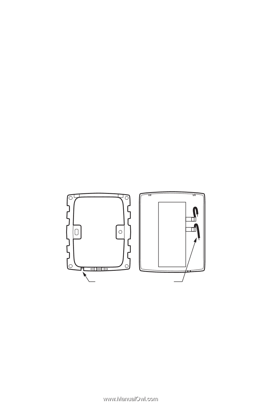
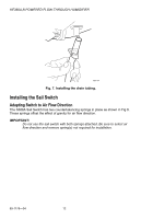
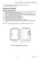
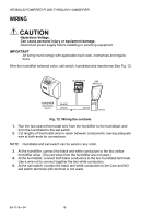
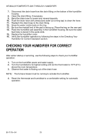
HE360A,B POWERED FLOW-THROUGH HUMIDIFIER 6. Secure the switch by using the sheet metal screws provided. 7. After wiring, snap on the cover. Installing the Humidistat Installing on Mounting Duct 1. Apply the template to the duct location chosen for the humidistat. Make sure the template is level before drilling the holes. 2. Refer to the template (provided with the H8908 Humidistat Installation Instructions) to drill the control assembly opening and mounting holes for the H8908. 3. Remove the H8908 case from the base. 4. Position the foam gasket on the H8908 base. 5. Position the base on the duct with the arrow up. 6. Secure the base to the duct using the four 1 in. (25 mm) mounting screws provided with humidistat. 7. Connect the low-voltage wires to the leads and replace the H8908 case. See Fig. 11. NOTE: For wall mounting instructions, see the H8908 Installation Instructions. HUMIDISTAT BASE REAR OF HUMIDISTAT WIRE SLOT HUMIDISTAT WIRES M20179 Fig. 11. Humidistat base and rear view. 15 69-1176-04
-
 1
1 -
2
-
3
-
4
-
5
-
6
-
7
-
8
-
9
-
 10
10 -
 11
11 -
 12
12 -
 13
13 -
 14
14 -
 15
15 -
 16
16 -
 17
17 -
 18
18 -
 19
19 -
 20
20 -
21
-
22
-
23
-
24
 |
 |