Honeywell WAVE2EX Setup Guide - Page 20
Data Field Descriptions
 |
UPC - 781410215504
View all Honeywell WAVE2EX manuals
Add to My Manuals
Save this manual to your list of manuals |
Page 20 highlights
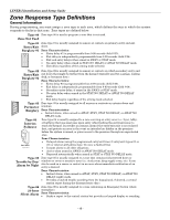
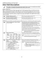
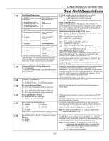
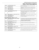
LYNXR-I Installation and Setup Guide Data Field Descriptions Defaults (where applicable) are Indicated in bold text. The following pages list all data fields in this Control (in numerical order). Use the blank programming form to record the data for this installation. Note that both keypad LEDs flash while in Programming mode. Note: Entering a number other than the one specified will give unpredictable results. ✻20 ✻21 ✻22 ✻23 ✻24 ✻25 ✻26 ✻27 ✻29 ✻30 ✻31 ✻32 ✻33 Installer Code Enter 4 digits, 0-9 The Installer Code is used to enter the 4-digit Master Security Code. See "Master Code" in the System Operation section for procedure. Quick Arm Enable 0 = do not allow quick arm 1 = allow quick arm If enabled, security code is not required to arm the system. The user simply presses and holds down the AWAY or STAY key to arm. Keypad Backlight Timeout 0 = no timeout; always backlight keys 1 = turn backlighting off after inactivity This option allows the choice of either always backlighting the keypad or turning the backlighting off after 10 seconds of keypad inactivity. Forced Bypass All zones bypassed by this function will be displayed after the 0 = no forced bypass bypass is initiated. 1 = provide automatic bypass of all open (faulted) zones UL installations: must be 0 (no forced bypass) RF House ID Code 00 = disable all wireless keypad usage 01-31 = House ID Powerline Carrier Device (X10) House ID 0=A 4=E 8=I # + 12 = M 1=B 5=F 9=J # + 13 = N 2 = C 6 = G # + 10 = K # + 14 = O 3 = D 7 = H # + 11 = L # + 15 = P The House ID identifies receivers and wireless keypads. If a 5804BD/5804BDV Transmitter is to be used, a House ID Code MUST be entered, and the keypad should be set to the same ID. Powerline Carrier Devices require a House ID. This field identifies this House ID to the Control. The Powerline Carrier Devices are programmed in field ✻80. Chime by Zone 0 = no (chimes on fault of any entry/exit or perimeter zone when Chime mode is activated 1 = yes (chimes on fault of those zones assigned to Zone List 3 when Chime mode on) This option allows the installer to define the specific zones intended to chime when faulted while the system is in Chime mode. If enabled, these zones are defined in zone list 3 (see ✻81 Zone List Menu Mode). Real Time Clock Display 0 = do not display the time 1 = display the time Refer to the User's Manual for setting the clock time and date. Daylight Savings Time Start/End Month 0, 0 = no daylight saving time used 1-12 = start month and end month Enter # + 10 for 10, # + 11 for 11, and # + 12 for 12. Daylight Savings Time Start/End Week 0 = disable 4 = fourth weekend 1 = first weekend of month 5 = last weekend 2 = second weekend 6 = next to last 3 = third weekend 7 = 3rd from last Single Alarm Sounding Per Zone (per armed period) 0 = no limit on alarm sounding per zone 1 = limit alarm sounding to once per arming period for a given zone Fire Sounder Timeout 0 = yes, fire sounder timeout after time programmed in field ✻33 1 = no fire sounder timeout; continue sounding until manually turned off Alarm Bell Timeout 0 = No timeout 2 = 8 min 1 = 4 min 3 = 12 min 4 = 16 min Enter the appropriate start and end weekend of the month. This field applies only to burglary zones (zone response types 15, 10), and affects long range radio reporting but does not affect central station reporting. Note: This field applies only to the bell and does not affect keypad sounds. UL installations: must be 0 (no limit) This Control complies with NFPA requirements for temporal pulse sounding of fire notification appliances. Temporal pulse sounding for a fire alarm consists of the following: 3 pulses - pause - 3 pulses - pause - 3 pulses. . . This field determines whether the external sounder will shut off after time allowed, or continue until manually turned off. UL installations: must be set for a minimum of 4 min (option 1) - 20 -
-
 1
1 -
2
-
3
-
4
-
5
-
6
-
7
-
8
-
9
-
10
-
11
-
12
-
13
-
14
-
 15
15 -
 16
16 -
 17
17 -
 18
18 -
 19
19 -
 20
20 -
 21
21 -
 22
22 -
 23
23 -
 24
24 -
 25
25 -
26
-
27
-
28
-
29
-
30
-
31
-
32
-
33
-
34
-
35
-
36
-
37
-
38
-
39
-
40
-
41
-
42
-
43
-
44
-
45
-
46
-
47
-
48
-
49
-
50
-
51
-
52
-
53
-
54
-
55
-
56
-
57
-
58
-
59
-
60
-
61
-
62
-
63
-
64
-
65
-
66
-
67
-
68
-
69
-
70
-
71
-
72
 |
 |
