Hunter 23298 Owner's Manual - Page 10
Warning, Caution - model #
 |
View all Hunter 23298 manuals
Add to My Manuals
Save this manual to your list of manuals |
Page 10 highlights
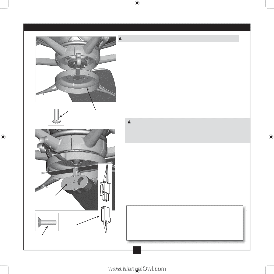
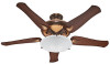
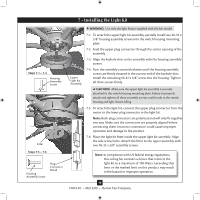
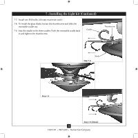
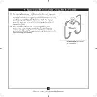
7 • Installing the Light Kit Steps 7-1 - 7-3 Housing Assembly Screw Fitter Steps 7-5 - 7-6 Housing Assembly Screw Plug Connector Detail Upper Light Kit Assembly WARNING: Use only the light fixture supplied with this fan model. 7-1. To attach the upper light kit assembly, partially install two #6-32 x 3/8" housing assembly screws into the switch housing mounting plate. 7-2. Feed the upper plug connector through the center opening of the assembly. 7-3. Align the keyhole slots in the assembly with the housing assembly screws. 7-4. Turn the assembly counterclockwise until the housing assembly screws are firmly situated in the narrow end of the keyhole slots. Install the remaining #6-32 x 3/8" screw into the housing. Tighten all three screws firmly. CAUTION: Make sure the upper light kit assembly is securely attached to the switch housing mounting plate. Failure to properly attach and tighten all three assembly screws could result in the switch housing and light fixture falling. 7-5. To attach the light kit, connect the upper plug connector from the motor to the lower plug connector in the light kit. Note: Both plug connectors are polarized and will only fit together one way. Make sure the connectors are properly aligned before connecting them. Incorrect connection could cause improper operation and damage to the product. 7-6. Place the light kit fitter inside the upper light kit assembly. Align the side screw holes. Attach the fitter to the upper assembly with two #6-32 x 3/8" assembly screws. Note: In compliance with US federal energy regulations, this ceiling fan contains a device that restricts the light kit to a maximum of 190 Watts. Exceeding that limit or the marked limit on this product may result in fire hazard or improper operation. 10 41874-01 • 08/13/09 • Hunter Fan Company
-
 1
1 -
2
-
3
-
4
-
 5
5 -
 6
6 -
 7
7 -
 8
8 -
 9
9 -
 10
10 -
 11
11 -
 12
12 -
 13
13 -
 14
14 -
 15
15 -
16
 |
 |