Hunter 44110 Owner's Manual - Page 19
Connecting The Wires
 |
View all Hunter 44110 manuals
Add to My Manuals
Save this manual to your list of manuals |
Page 19 highlights
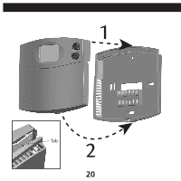
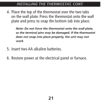
INSTALLING THE THERMOSTAT, CONT. CONNECTING THE WIRES 1. Loosen, but do not remove, the terminal screws. Jumper G RC RH Y W Note: A jumper wire has been provided, connecting the RC and RH terminals for systems that do not provide both an RH and RC wire. If you have both an RH and RC wire, remove this jumper. If you do not have both an RH and RC wire, leave the jumper in place. 2. Match and connect the wires from the wall to the terminals as shown. Wires should be inserted behind the black terminal shields. Tighten each screw after the connection has been made. (The ends of any extra wires should be wrapped in electrical tape and carefully pushed back into the wall.) 3. Push any excess wire length back into the wall to prevent interference. 17
-
 1
1 -
2
-
3
-
4
-
5
-
6
-
7
-
8
-
9
-
10
-
11
-
12
-
13
-
 14
14 -
 15
15 -
 16
16 -
 17
17 -
 18
18 -
 19
19 -
 20
20 -
 21
21 -
 22
22 -
 23
23 -
 24
24 -
25
-
26
-
27
-
28
-
29
-
30
-
31
-
32
-
33
-
34
-
35
-
36
-
37
-
38
-
39
-
40
-
41
-
42
-
43
-
44
-
45
-
46
-
47
-
48
-
49
-
50
-
51
-
52
-
53
-
54
 |
 |
