Hunter 44860 Owner's Manual - Page 12
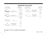
See s 74 for a complete wiring diagram. - heat pump not cooling
 |
View all Hunter 44860 manuals
Add to My Manuals
Save this manual to your list of manuals |
Page 12 highlights
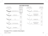
if your existing thermostat is marked: HEAT PUMP SYSTEMS label the wire with this sticker: if your existing thermostat is marked: label the wire with this sticker: Y1 / Y2 Compressor Stage 1 or 2 Y1 Y2 Y2 Y1 C 24 VAC Common C C O W2 Auxilliary Heat W2 W2 O Cool Mode Powered Reverse Valve O G Fan G G E Emergency Heat E E R/RC R / RC 24 VAC Power Supply R/RC B B Heat Mode Powered Reverse Valve B L L System Monitor L See pages 74 for a complete wiring diagram. 44002-01 r051807 11
-
 1
1 -
2
-
3
-
4
-
5
-
6
-
 7
7 -
 8
8 -
 9
9 -
 10
10 -
 11
11 -
 12
12 -
 13
13 -
 14
14 -
 15
15 -
 16
16 -
 17
17 -
18
-
19
-
20
-
21
-
22
-
23
-
24
-
25
-
26
-
27
-
28
-
29
-
30
-
31
-
32
-
33
-
34
-
35
-
36
-
37
-
38
-
39
-
40
-
41
-
42
-
43
-
44
-
45
-
46
-
47
-
48
-
49
-
50
-
51
-
52
-
53
-
54
-
55
-
56
-
57
-
58
-
59
-
60
-
61
-
62
-
63
-
64
-
65
-
66
-
67
-
68
-
69
-
70
-
71
-
72
-
73
-
74
-
75
-
76
 |
 |

11
if your existing
thermostat is marked:
label the wire
with this sticker:
R / RC
R/RC
R/RC
24 VAC Power Supply
Y1 / Y2
Compressor Stage 1 or 2
W2
W2
W2
Auxilliary Heat
E
E
E
Emergency Heat
C
C
C
24 VAC Common
HEAT PUMP SYSTEMS
O
O
O
Cool Mode Powered
Reverse Valve
B
B
B
Heat Mode Powered
Reverse Valve
G
G
G
Fan
L
L
L
System Monitor
if your existing
thermostat is marked:
label the wire
with this sticker:
Y1
Y2
Y2
Y1
Y1
Y2
See pages 74 for a complete wiring diagram.
44002-01 r051807