Husqvarna V548 - 2023 Owner Manual - Page 19
Tire pressure, To remove and install the front wheels, To adjust the anti-scalp rollers
 |
View all Husqvarna V548 - 2023 manuals
Add to My Manuals
Save this manual to your list of manuals |
Page 19 highlights
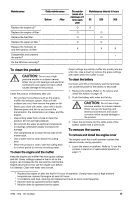
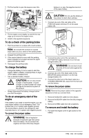
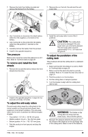
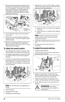
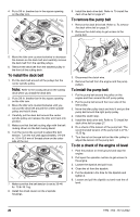
2. Remove the knob from battery bracket and remove the bracket from the battery. 2. Remove the nut, the bolt, the axle and the antiscalp roller. 3. Use 2 wrenches to disconnect the black battery cable from the negative (-) terminal on the battery. 4. Use 2 wrenches to disconnect the red battery cable from the positive (+) terminal on the battery. 5. Carefully remove the battery from the product. 6. Install in the opposite sequence. Tire pressure Make sure to have the correct tire pressure on all 4 tires. Refer to Technical data on page 29. To remove and install the front wheels 1. Remove the nut and the bolt to remove the front wheels from the forks. 3. Install the anti-scalp roller in one of the 3 positions. CAUTION: The cutting deck can become damaged if the antiscalp rollers are incorrectly adjusted. The anti-scalp rollers must be approximately 1/4 in. / 6.4 mm from the ground. To adjust the parallelism of the cutting deck This procedure will set the cutting deck in a standard position. 1. Make sure that the tire pressure is correct. Refer to Technical data on page 29. 2. Make sure that the deck drive belt is correctly installed. Refer to To install the deck drive belt on page 21. 3. Park the product on a level surface. 4. Put the cutting deck in transport position. 5. Turn the blades to align with the cutting deck side to side. 2. Install in the opposite sequence. Torque the nut and bolt to 50 ft-lbs / 67.8 Nm. To adjust the anti-scalp rollers The anti-scalp rollers keep the cutting deck in the correct position on the ground and prevent lawn scalping in most terrain conditions. The anti-scalp rollers can be set in 3 positions for different lengths of grass: • Top position: 1.5-2.5 in. / 38-64 mm grass. • Middle position: 2.5-4 in. / 64-102 mm grass. • Bottom position: 4-5 in. / 102-127 mm grass. 1. Park the product on level ground and stop the engine. WARNING: The blades on the cutting deck are sharp and can cause injury. Use protective gloves. 6. Measure the distance between the ground and the bottom of the blade tip on the discharge side of the cutting deck. Make a note of the distance. 1994 - 002 - 05.12.2022 19
-
 1
1 -
2
-
3
-
4
-
5
-
6
-
7
-
8
-
9
-
10
-
11
-
12
-
13
-
 14
14 -
 15
15 -
 16
16 -
 17
17 -
 18
18 -
 19
19 -
 20
20 -
 21
21 -
 22
22 -
 23
23 -
 24
24 -
25
-
26
-
27
-
28
-
29
-
30
-
31
-
32
-
33
-
34
-
35
-
36
-
37
-
38
-
39
-
40
-
41
-
42
-
43
-
44
-
45
-
46
-
47
-
48
-
49
-
50
-
51
-
52
-
53
-
54
-
55
-
56
-
57
-
58
-
59
-
60
-
61
-
62
-
63
-
64
-
65
-
66
-
67
-
68
 |
 |
